Balance and/or gait perturbation system and a method for testing and/or training a subject using the same
- Summary
- Abstract
- Description
- Claims
- Application Information
AI Technical Summary
Benefits of technology
Problems solved by technology
Method used
Image
Examples
first embodiment
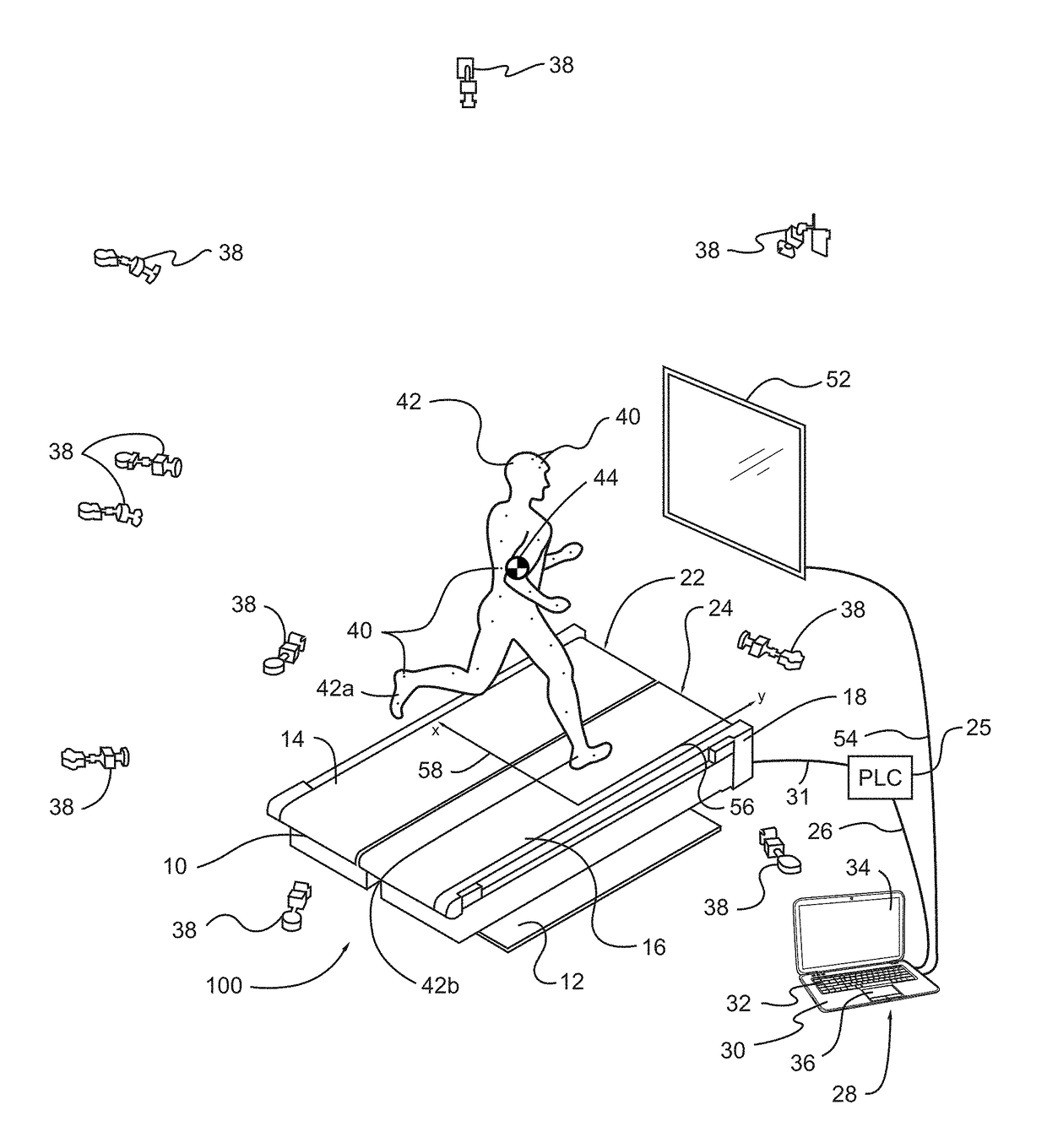
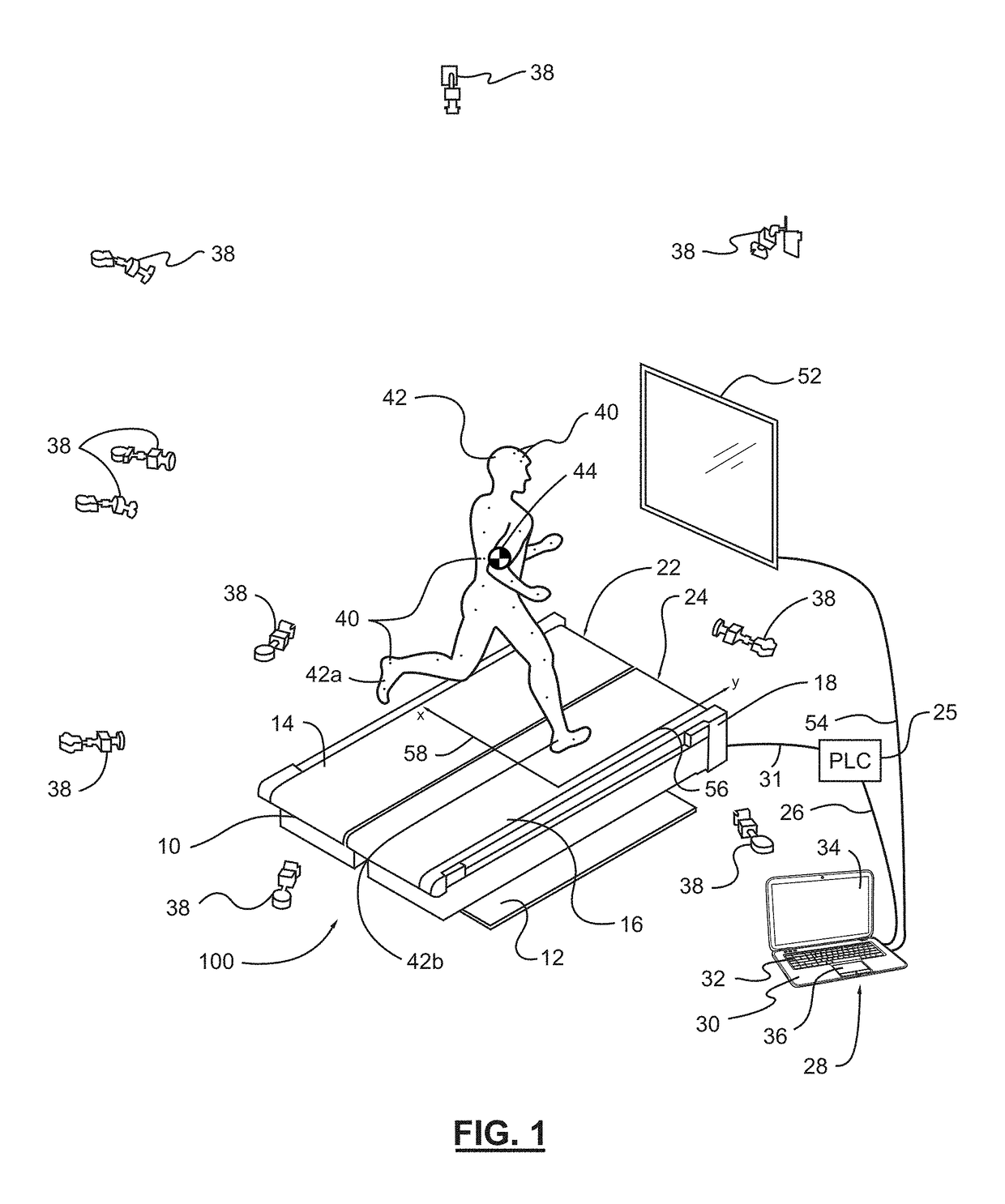
[0032]FIG. 1 is a perspective view of a gait perturbation system with a gait perturbation device in the form of an instrumented treadmill, according to the invention;
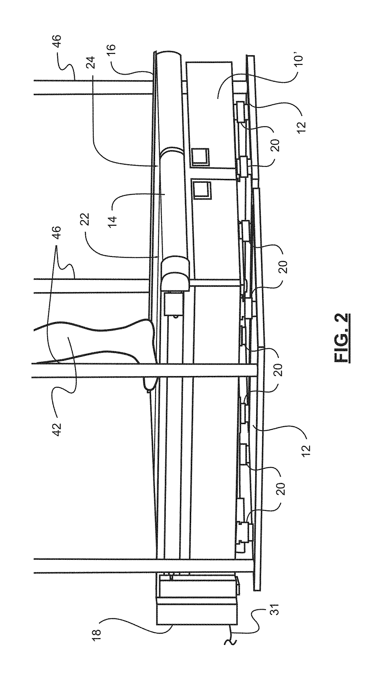
[0033]FIG. 2 is an end-side perspective view illustrating the pylon-type force transducers of the instrumented treadmill of FIG. 1, wherein, in this figure, handrails have been added to the instrumented treadmill of FIG. 1;
[0034]FIG. 3 is a side view illustrating the instrumented treadmill of FIG. 2;
[0035]FIG. 4 is another perspective view of a subject disposed on the instrumented treadmill of FIG. 1, wherein the subject is outfitted with a plurality of inertial measurement units (IMUs) thereon;
[0036]FIG. 5 is a block diagram of constituent components of the gait perturbation system with the instrumented treadmill of FIG. 1, according to an embodiment of the invention;
[0037]FIG. 6 is a block diagram illustrating the electronic actuator components of the instrumented treadmill of FIG. 1, and the data manipulation operati...
second embodiment
[0049]FIG. 18 is a perspective view of a balance perturbation system with a balance perturbation device in the form of a displaceable force measurement assembly, according to the invention;
[0050]FIG. 19 is a perspective view of an immersive subject visual display device, a base assembly, and displaceable force measurement assembly of the balance perturbation system of FIG. 18;
[0051]FIG. 20 is a perspective view of an immersive subject visual display device and a cutaway perspective view of a base assembly and displaceable force measurement assembly of the balance perturbation system of FIG. 18, wherein several covers of the base assembly are removed;
[0052]FIG. 21 is a top view of the base assembly illustrated in FIGS. 19 and 20, according to the second embodiment of the invention;
[0053]FIG. 22 is a longitudinal section cut through the base assembly illustrated in FIG. 21, wherein the section is cut along the cutting plane line A-A in FIG. 21, according to the second embodiment of th...
PUM
 Abstract
Description
Claims
Application Information
 - R&D
- Intellectual Property
- Life Sciences
- Materials
- Tech Scout
- Unparalleled Data Quality
- Higher Quality Content
- 60% Fewer Hallucinations
Browse by: Latest US Patents, China's latest patents, Technical Efficacy Thesaurus, Application Domain, Technology Topic, Popular Technical Reports.
© 2025 PatSnap. All rights reserved.Legal|Privacy policy|Modern Slavery Act Transparency Statement|Sitemap|About US| Contact US: help@patsnap.com


