System for reducing vibrations in a pressure pumping fleet

a technology of pressure pumping and vibration reduction, which is applied in the direction of positive displacement liquid engines, liquid fuel engines, borehole/well accessories, etc., can solve the problems of large vibrations of both high and low frequencies, large vibrations of low frequencies, so as to reduce turbulence and vibrations, reduce vibration and vibration, and simplify the fluid dynamic flow

Active Publication Date: 2018-11-06
US WELL SERVICS LLC
View PDF236 Cites 164 Cited by
  • Summary
  • Abstract
  • Description
  • Claims
  • Application Information

AI Technical Summary

Benefits of technology

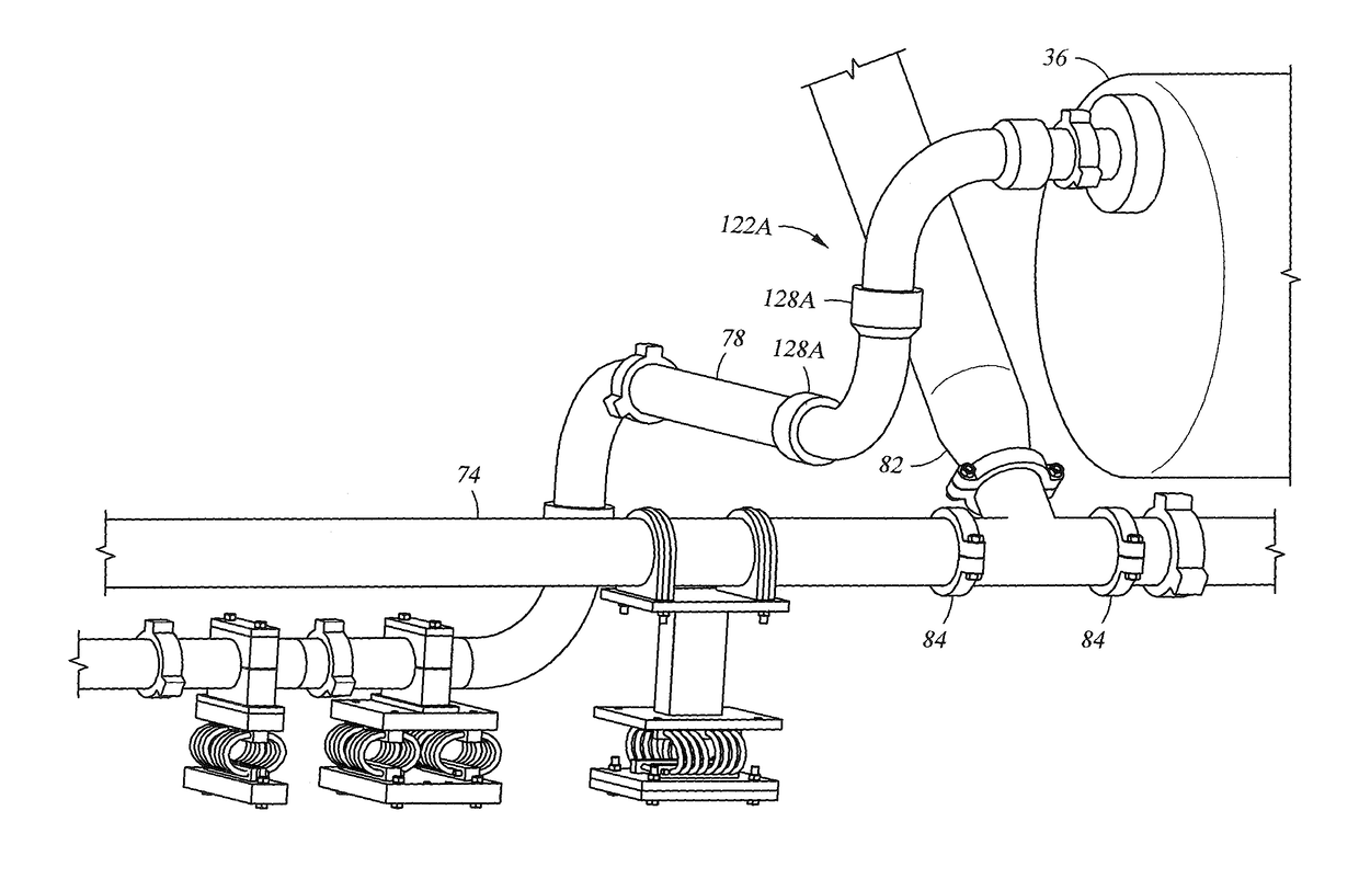
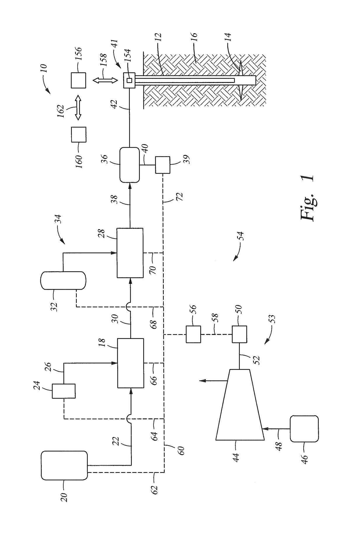
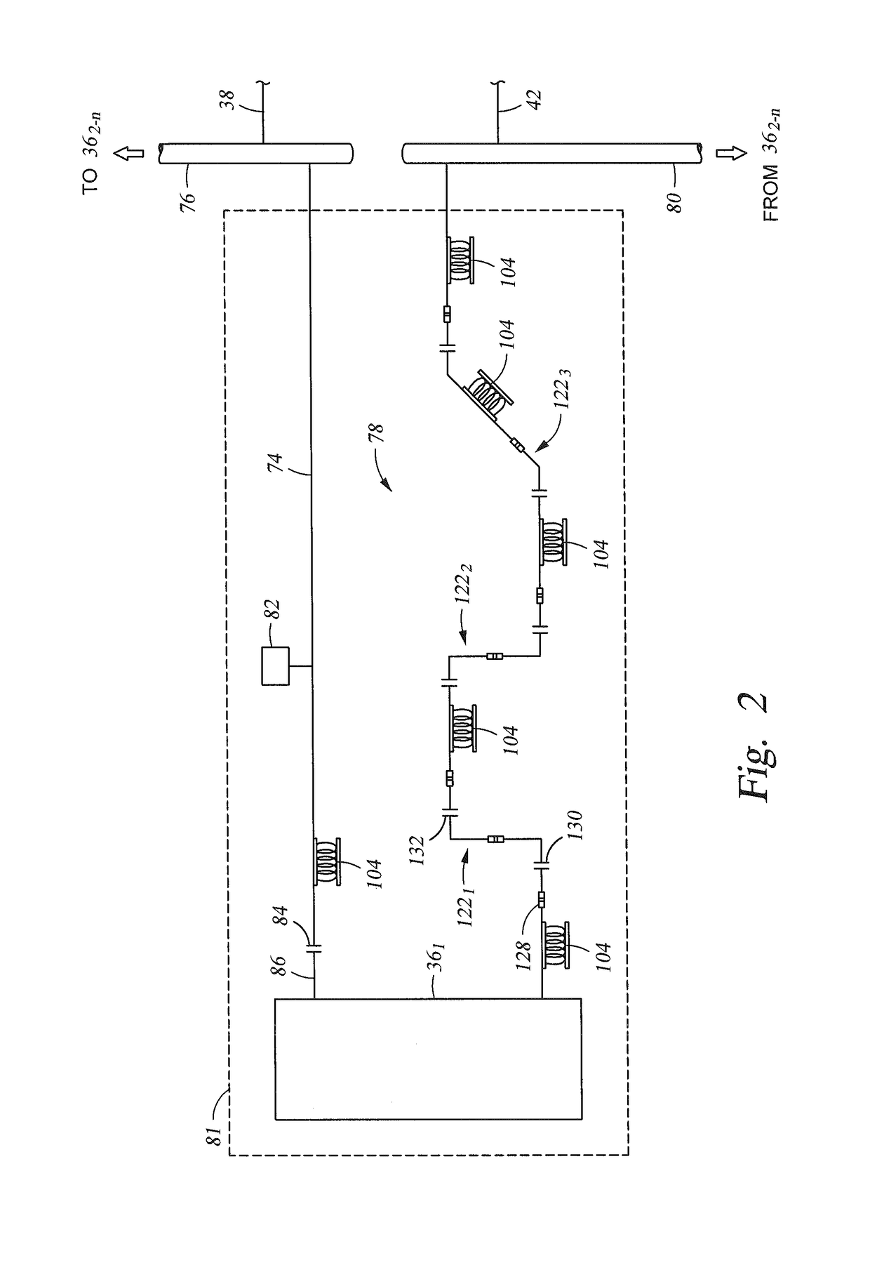
[0007]Disclosed herein is an example of a hydraulic fracturing system for fracturing a subterranean formation, and which includes an electrically powered fracturing pump having a suction side and a discharge side, a suction branch of piping having fracturing fluid therein, a discharge branch of piping having therein pressurized fracturing fluid supplied from the fracturing pump, a tubular suction lead having an end mounted to the suction side and an opposite end coupled to an end of the suction branch by a grooved connection, and which is pivotal with respect to the suction branch, swivel connections strategically located in the discharge branch of piping, so that when pressurized fracturing fluid flows through the discharge branch of piping, a section of the discharge branch of piping is axially rotatable with an adjacent section of the discharge branch of piping, and helical coils supporting suction and discharge branches of piping at strategically located positions. In one embodiment; engines, transmissions, large cooling fans, and u-joint drive shafts are intentionally not included to minimize both high and low frequency vibrations. At least one of the helical coils can have an axis that is disposed oblique with an axis of an adjacent amount of piping. Optionally included is a pulsation dampener in fluid communication with the suction branch and adjacent the suction lead. In one example the fracturing pump is a first fracturing pump, wherein the suction and discharge branches respectively intersect with suction and discharge piping that are in fluid communication with a second fracturing pump, and wherein the suction and discharge branch intersections are at locations that are each spaced away from a surface on which the first fracturing pump is supported. The surface on which the first fracturing pump is supported can be a trailer, truck, skid, or other platform. In one example, the hydraulic fracturing pump unit has two fracturing pumps where the suction piping for the first pump and the suction piping for the second pump are separate and distinct. This allows for a much simpler fluid dynamic flow that reduces turbulence and vibrations. In another example, the discharge piping for the first pump and the discharge piping for the second pump are separate and distinct from the pump to the edge of the unit. This allows for a simpler fluid dynamic flow that reduces turbulence and vibrations. The hydraulic fracturing system can further include a turbo-generator or other power source and power distribution equipment for generating and distributing electricity used for powering the fracturing pump.
[0008]Also disclosed herein is an example of a method of hydraulically fracturing a subterranean formation, and which includes pressurizing fracturing fluid with a hydraulic fracturing system that comprises an electrically powered fracturing pump, a tubular suction branch, and a tubular discharge branch, drawing the fracturing fluid into the fracturing pump through the suction branch, discharging the fracturing fluid from the fracturing pump through the discharge branch, introducing the fracturing fluid to the formation to create a fracture in the formation, and reducing vibration in the hydraulic fracturing system by, strategically locating swivel joints in the suction and discharge branches, so that designated sections of the suction and discharge branches are moveable with respect to other sections of the suction and discharge branches, providing a grooved connection in the suction branch, so that piping supplying fracturing fluid to the fracturing pump is pivotable with respect to the fracturing pump, maintaining portions of the suction and discharge branches that are supported on a surface that supports the fracturing pump from other suction and discharge branches, and resting the suction and discharge branches on helical coils. The method can further include providing an elastomeric yoke with the helical coils. Optionally, some of the fluid in the suction branch can be routed to an accumulator. The method can further include powering the fracturing pump with electricity generated by a turbo-generator or other power supply.
[0009]An alternate example of a method of hydraulically fracturing a subterranean formation includes pressurizing fracturing fluid with a hydraulic fracturing system that includes an electrically powered fracturing pump and piping coupled with the fracturing pump, discharging pressurized fracturing fluid for delivery to a wellbore that intersects the formation so that the pressurized fracturing fluid fractures the formation, and reducing vibration in the hydraulic fracturing system by providing joints in the piping at strategic locations so that adjacent sections of the piping pivot and / or swivel. The joints can include a swiveling joint that allows relative rotational movement between adjacent sections of the piping. The joints are made up of a grooved connection joint that allows pivoting between adjacent sections of the piping. The method can further include maintaining the piping separate from piping that is in fluid communication with another fracturing pump. In one example, the traditional engine and transmission are replaced by a variable frequency drive (“VFD”) and an electric motor. Then the traditional u-joint drive line, which requires at least a three degree offset from the horizontal output of the transmission with the horizontal input of the hydraulic fracturing pump, is replaced by a direct coupling to reduce or eliminate the vibrations caused by the required misalignment that the traditional u-joint drive shaft requires.

Problems solved by technology

The diesel engines and transmission which power hydraulic fracturing units typically generate large amounts of vibrations of both high and low frequencies.
These vibrations are generated by the diesel engine, the transmission, the hydraulic fracturing pump as well as the large cooling fan and radiator needed to cool the engine and transmission.
Low frequency vibrations and harshness are greatly increased by the large cooling fans and radiator required to cool the diesel engine and transmission.
Diesel powered hydraulic fracturing units are known to jack and jump while operating in the field from the large amounts of vibrations.
The vibrations may contribute to fatigue failures of many differed parts of a hydraulic fracturing unit.
Because of the high pressures generated by the pumps, and that the pumps used for pressurizing the fracturing fluid are reciprocating pumps, a significant amount of vibration is created when pressurizing the fracturing fluid.
The vibration transmits to the piping that carries the fracturing fluid and its associated equipment, thereby increasing probabilities of mechanical failure for the piping and equipment, and also shortening their useful operational time.

Method used


Image

  • System for reducing vibrations in a pressure pumping fleet
  • System for reducing vibrations in a pressure pumping fleet
  • System for reducing vibrations in a pressure pumping fleet

Examples


Embodiment Construction

[0020]The method and system of the present disclosure will now be described more fully hereinafter with reference to the accompanying drawings in which embodiments are shown. The method and system of the present disclosure may be in many different forms and should not be construed as limited to the illustrated embodiments set forth herein; rather, these embodiments are provided so that this disclosure will be thorough and complete, and will fully convey its scope to those skilled in the art. Like numbers refer to like elements throughout. In an embodiment, usage of the term “about” includes + / −5% of the cited magnitude. In an embodiment, usage of the term “substantially” includes + / −5% of the cited magnitude.

[0021]It is to be further understood that the scope of the present disclosure is not limited to the exact details of construction, operation, exact materials, or embodiments shown and described, as modifications and equivalents will be apparent to one skilled in the art. In the ...


PUM


Abstract

An electrically powered hydraulic fracturing system having pumps for pressurizing fracturing fluid, piping for carrying fracturing fluid, and vibration reducing equipment for use with the piping. The vibration reducing equipment includes helical coils that support the piping. The coils are made of a wire rope made of strands of steel cable twisted together. Grooved fittings are provided on some piping connections, and which allow pivoting between adjacent fluid conveyance members. Swivel joints are strategically located in the piping which allow rotational flexing between adjacent sections of the piping; thereby attenuating vibration in the piping but without stressing the piping.

Description

CROSS REFERENCE TO RELATED APPLICATIONS[0001]This application is a continuation of, and claims priority to and the benefit of, U.S. Provisional Application Ser. No. 62 / 156,306, filed May 3, 2015 and is a continuation-in-part of, and claims priority to and the benefit of co-pending U.S. patent application Ser. No. 13 / 679,689, filed Nov. 16, 2012, the full disclosures of which are hereby incorporated by reference herein for all purposes.BACKGROUND OF THE INVENTION[0002]1. Field of Invention[0003]The present disclosure relates to hydraulic fracturing of subterranean formations. In particular, the present disclosure relates to methods and devices for reducing vibration during hydraulic fracturing of a subterranean formation.[0004]2. Description of Prior Art[0005]Hydraulic fracturing is a technique used to stimulate production from some hydrocarbon producing wells. The technique usually involves injecting fluid into a wellbore at a pressure sufficient to generate fissures in the formatio...

Claims


Application Information

Patent Timeline
Patent Type & Authority Patents(United States)
IPC IPC(8): E21B43/26F04B17/03F01D15/08F16L55/04F16F15/067F01D15/10F04B19/22F04B49/20F02C3/22H02P23/00F04B23/04F04B47/00F16F3/04
CPCE21B43/26F01D15/08F01D15/10F02C3/22F04B17/03F04B19/22F04B47/00F04B49/20F16F15/067F16L55/041H02P23/00F04B23/04F16F3/04F05D2220/32F04B23/00F04B53/003E21B43/2607
Inventor OEHRING, JAREDKURTZ, ROBERT
Owner US WELL SERVICS LLC
Why Eureka
Try Eureka