Lock-up-clutch control device

a control device and lock-up-clutch technology, which is applied in the direction of clutches, gearing elements, gearing, etc., can solve the problems of excessive clutch capacity, rapid drop of engine rotation speed, and inability to treat with a case where the engine torque is reduced, so as to promote the increase of reduce the engaging capacity of the lock-up-clutch, and increase the engaging capacity.

Active Publication Date: 2018-11-13
JATCO LTD +1
View PDF12 Cites 3 Cited by
  • Summary
  • Abstract
  • Description
  • Claims
  • Application Information

AI Technical Summary

Benefits of technology

[0012](1) In order to achieve the objects, the present invention provides a control device for a lock-up-clutch installed in a torque converter arranged between a prime mover serving as a driving source and an automatic transmission mechanism, the control device including an engagement control means that carries out a calculation to increase an engaging capacity of the lock-up-clutch with the passage of time during an engagement control time in which the torque converter is shifted from a converter condition to a lock-up condition, the prime mover driving an auxiliary device, in which when, during the control to increase the engaging capacity of the lock-up-clutch, an input torque inputted to the torque converter from the prime mover is increased due to reduction in load of the auxiliary device, the engagement control means promotes the increase of the engaging capacity of the lock-up-clutch based on the amount of increase of the input torque.
[0017](6) The present invention provides another control device for a lock-up-clutch installed in a torque converter arranged between a prime mover serving as a driving source and an automatic transmission mechanism, the control device including an engaging capacity calculation means that carries out a calculation to increase an engaging capacity of the lock-up-clutch with the passage of time during an engagement control time in which the torque converter is shifted from a converter condition to a lock-up condition and an engagement control means that controls the engaging pressure of the lock-up-clutch based on the engaging capacity thus calculated, in which the control device further includes an accelerator open degree detecting means that detects an accelerator open degree of the motor vehicle an open degree reduction judgment means that judges whether the accelerator open degree detected by the accelerator is decreased or not; an input torque estimation means that estimates the input torque inputted to the torque converter from the prime mover; and a torque increase judgment means that judges whether the input torque thus estimated is increased or not, in which when reduction of the accelerator open degree is judged, the engaging capacity calculation means reduces the engaging capacity of the lock-up-clutch based on the amount of reduction of the open degree, and when no reduction of the accelerator open degree is judged and increase of the input torque is judged, the engaging capacity calculation means promotes the increase of the engaging capacity of the lock-up-clutch.
[0018]In the control device for a lock-up-clutch of the present invention, when, during the time for which the engaging capacity of the lock-up-clutch is controlled to be increased, the input torque inputted to the torque converter from the prime mover is increased, increasing the engaging capacity of the lock-up-clutch is promoted based on the amount of increase of the torque, so that in case of such torque increase, undesirable pressure shortage that would be produced in a period from the converter condition to the lock-up condition can be avoided.
[0019]Furthermore, when the accelerator open degree is reduced, a control by which the engaging capacity of the lock-up-clutch is reduced based on the amount of reduction of the open degree is carried out while taking priority over other controls, and thus, undesired clutch capacity excessiveness caused by a step-returning of the accelerator pedal can be assuredly avoided.

Problems solved by technology

However, in case of using the control in which the predetermined amount of change is periodically increased to increase the fastening engaging capacity thereby to increase the lock-up-clutch engaging pressure, it is impossible to treat with a case wherein the engine torque is reduced due to closing of a throttle (or accelerator pedal) under the control.
Accordingly, the clutch capacity becomes excessive and thus, an engagement shock, a rapid drop of engine rotation speed and the like tend to occur.
Accordingly, in case of the disclosed technique, undesired pressure shortage phenomenon that would be induced in a transition time for the lock-up condition can't be avoided.
Particularly, in case where the engine output torque is lowered upon the step-returning action of the accelerator pedal, the torque inputted to the torque converter is reduced and thus the pressure by which the lock-up-clutch is perfectly engaged is lowered, and thus, the clutch capacity becomes excessive thereby bringing about a rapid perfect engaging of the lock-up-clutch and appearance of the engagement shock and a rapid drop of the engine speed.
In the invention disclosed by Patent Document 1, the fastening condition of the lock-up-clutch is controlled based on an engine output torque that is calculated from a degree of the throttle opening appearing as the result of the step-returning action of the accelerator pedal, and thus, controlling the lock-up-clutch tends to produce a control delay due to a response delay of the hydraulic pressure used for the clutch fastening control.
Accordingly, the undesired engagement shock tends to occur before the lock-up-clutch fastening pressure is lowered.

Method used


Image

  • Lock-up-clutch control device
  • Lock-up-clutch control device
  • Lock-up-clutch control device

Examples


Embodiment Construction

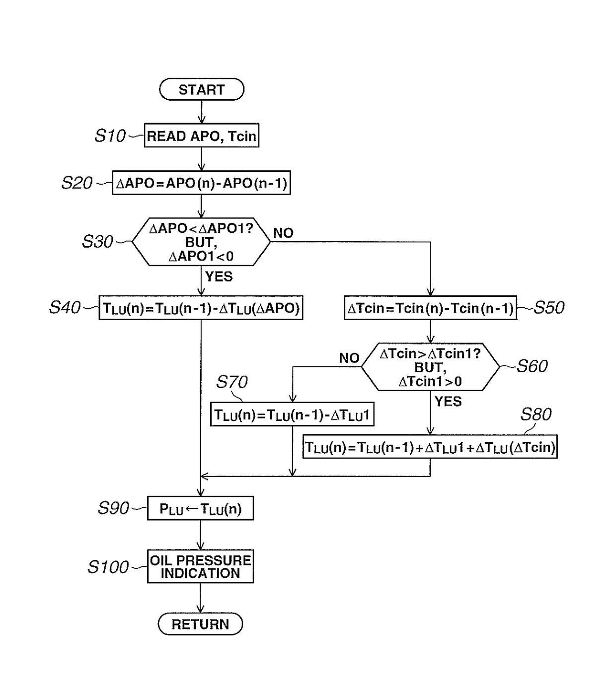
[0027]In the following, an embodiment of the present invention will be described with reference to the attached drawings.

[0028]It is to be noted that the embodiment described in the following is only an example and elimination of application of various deformations and technologies, that are not clearly described in the following explanation, from the invention is not intended.

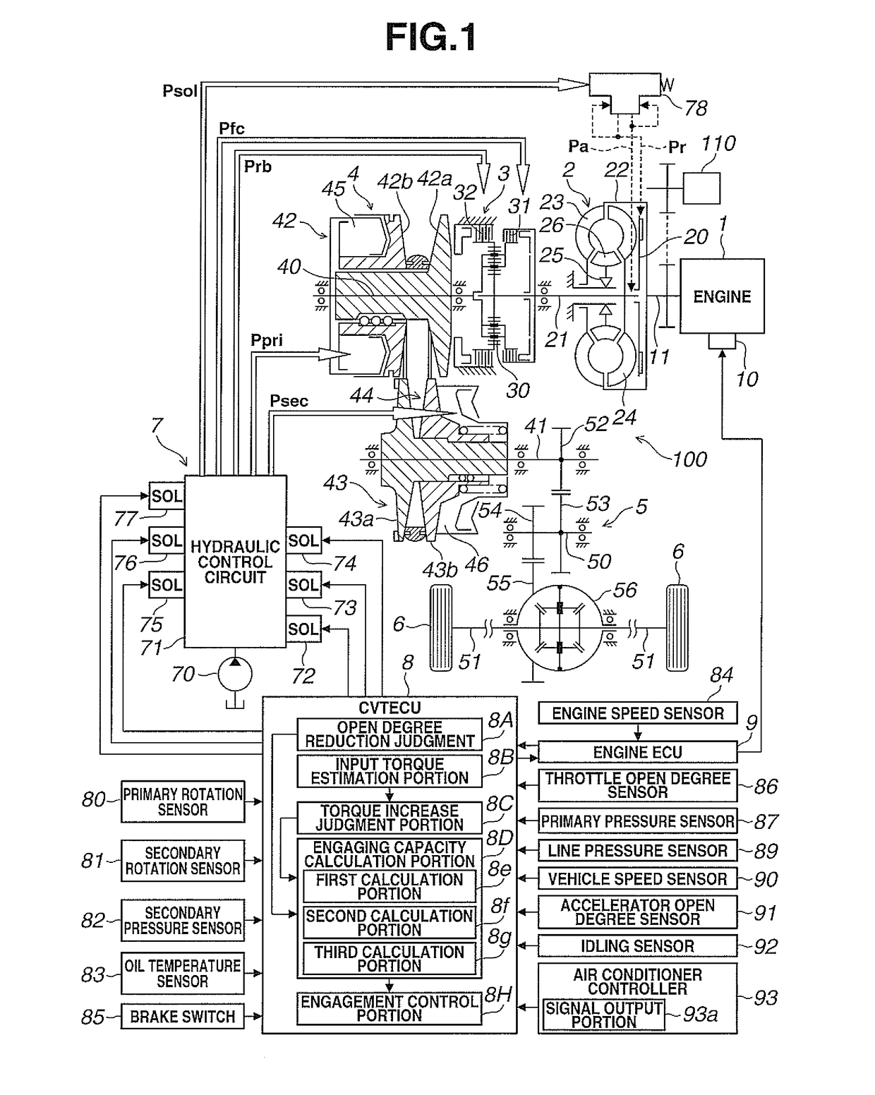
[0029]First, the construction of a driving system and a control system of a motor vehicle to which the lock-up-clutch control device of the embodiment is practically applied will be described. Although, in the embodiment, an example using, as an automatic transmission, a belt-type continuously variable transmission (which will be referred to as belt-type CVT or just CVT in the following) is used, the other type continuously variable transmissions, such as a toroidal CVT or the like and stepped automatic transmissions can be used.

[0030][Overall System Construction]

[0031]FIG. 1 is a construction view showing a d...


PUM


Abstract

A control device for a lock-up-clutch installed in a torque converter arranged between an engine and an automatic transmission mechanism includes an engagement control means that carries out a calculation to increase an engaging capacity of the lock-up-clutch with the passage of time during an engagement control time in which the torque converter is shifted from a converter condition to a lock-up condition in which the prime mover drives an auxiliary device and in which when, during the control to increase the engaging capacity of the lock-up-clutch, an input torque to the torque converter from the engine is increased due to reduction in load of the auxiliary device, the engagement control means promotes the increase of the engaging capacity of the lock-up-clutch based on the amount of increase of the input torque thereby eliminating undesired pressure shortage that would be induced in the period toward the lock-up condition.

Description

TECHNICAL FIELD[0001]The present invention relates to a control device for a lock-up-clutch installed in a motor vehicle.BACKGROUND ART[0002]In motor vehicles, such as cars or the like, that have between an engine and an automatic transmission mechanism a torque converter, there is a type where the torque converter is equipped with a lock-up-clutch for reducing deterioration of fuel consumption which would be caused by a slippage of the torque converter. The lock-up-clutch has, as operation conditions, a lock-up condition wherein input and output elements are directly engaged, a converter condition wherein the input and output elements are fully disengaged to effect a torque transmission through a fluid, and a slip condition wherein the lock-up-clutch is made in a half-engagement condition to keep a given slip condition.[0003]For controlling the lock-up-clutch, the above-mentioned three operation conditions are suitably switched in accordance with an operation condition of the vehic...

Claims


Application Information

Patent Timeline
Patent Type & Authority Patents(United States)
IPC IPC(8): F16D48/06F16H61/14F16H45/02
CPCF16H61/143F16D48/06Y10T477/635F16D2500/3144F16H2061/145F16D2500/1045F16D2500/10412F16D2500/30412Y10T477/73F16D2500/7082F16D2500/70426F16H45/02F16H2059/145F16H59/14F16H59/18F16H61/14F16H2059/147
Inventor HONMA, TOMOAKIKAMIYA, KOHEISUZUKI, YUTASHINOHARA, ITARUSEKIYA, HIROSHIOGINO, HIROMUENDO, YASUHIROTOHTA, YUZURUSAITOU, KOUKI
Owner JATCO LTD
Why Eureka
Try Eureka