
Film capacitor and the method of forming the same

a film capacitor and capacitor technology, applied in the field of capacitors, can solve the problems of low temperature ratings, difficulty in heat removal, and loss of volts dc to 1000 volts dc, and achieve the effect of high ripple current environmen

Active Publication Date: 2018-11-13
GENERAL ELECTRIC CO
View PDF18 Cites 3 Cited by
  • Summary
  • Abstract
  • Description
  • Claims
  • Application Information

AI Technical Summary

Problems solved by technology

For example, some commercially available capacitors that are capable of handling higher voltage ratings (for example, 250 Volts DC to 1000 Volts DC) may suffer from low temperature ratings and difficulty in heat removal.
Sometimes, exposure to such steep temperature rise degrades performance of the capacitors.
In certain cases, the capacitor may fail to operate and may even burn down, thereby leading to a hazardous situation.
Such cooling systems may not only add considerable complexity, but may also increase system volume, weight, and cost.
Continued reliance on such cooling systems to overcome the low temperature limitations of the current commercial capacitors may not meet the increasing demand for smaller, lighter, and high-power electrical systems.

Method used


Image

  • Film capacitor and the method of forming the same
  • Film capacitor and the method of forming the same
  • Film capacitor and the method of forming the same

Examples


Embodiment Construction

[0026]The specification may be best understood with reference to the detailed figures and description set forth herein. Various embodiments are described hereinafter with reference to the figures. However, those skilled in the art will readily appreciate that the detailed description given herein with respect to these figures is for explanatory purposes as the method and the system may extend beyond the described embodiments.

[0027]Unless defined otherwise, technical and scientific terms used herein have the same meaning as is commonly understood by one of ordinary skill in the art to which this disclosure belongs. In the following specification and the claims, the singular forms “a”, “an” and “the” include plural referents unless the context clearly dictates otherwise. As used herein, the term “or” is not meant to be exclusive and refers to at least one of the referenced components being present and includes instances in which a combination of the referenced components may be presen...


PUM


Abstract

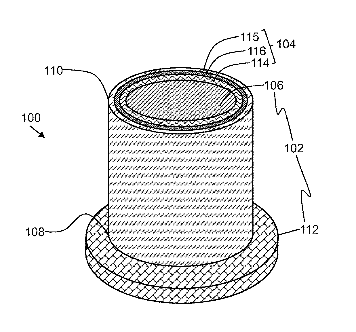
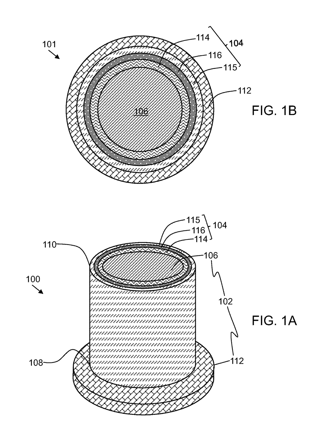
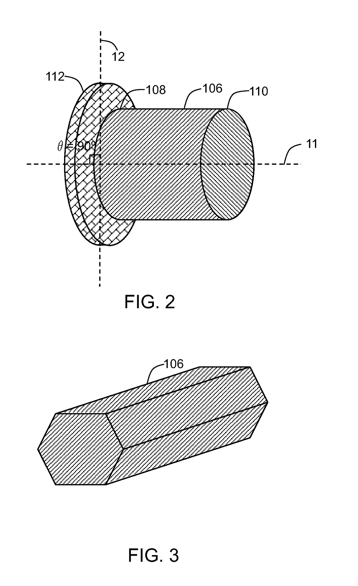
A film capacitor is presented. The film capacitor includes a thermally conductive support. The thermally conductive support includes a core including a first end and a second end. The thermally conductive support further includes a protrusion extending from at least one of the first end and the second end of the core, where at least one of the core and the protrusion includes a phase change material. Further, the film capacitor also includes a plurality of films disposed on at least a portion of the thermally conductive support, where the plurality of films includes a plurality of electrode films and a dielectric film. Further, the thermally conductive support for the film capacitor and a method of forming the film capacitor are also presented.

Description

STATEMENT REGARDING FEDERALLY SPONSORED RESEARCH AND DEVELOPMENT[0001]This invention was made with Government support under contract number DE-EE0006433 awarded by the U.S. Department of Energy. The Government has certain rights in the invention.BACKGROUND[0002]Embodiments of the disclosure relate to capacitors. More particularly, embodiments of the disclosure relate to a film capacitor having a thermally conductive support and a method of forming the film capacitor.[0003]Capacitors, such as, film capacitors, are often found in numerous electronic circuits. In some applications, these capacitors are subject to increased temperatures caused due to an external environment, ripple current pulses, or both. For example, some commercially available capacitors that are capable of handling higher voltage ratings (for example, 250 Volts DC to 1000 Volts DC) may suffer from low temperature ratings and difficulty in heat removal. For a given ambient condition, an internal temperature of a capa...

Claims


Application Information

Patent Timeline
Patent Type & Authority Patents(United States)
IPC IPC(8): H01G4/33H01G4/005H01G4/28H01G4/32H01G2/08H01G4/258
CPCH01G4/005H01G2/08H01G4/33H01G4/32H01G4/258H01G4/28
Inventor TAN, DANIEL QIZHANG, LILISMOLENSKI, JOSEPH LUCIANSULLIVAN, JEFFREY S
Owner GENERAL ELECTRIC CO
Learn More