Method and apparatus for bi-directional switched mode power supply with fixed frequency operation
- Summary
- Abstract
- Description
- Claims
- Application Information
AI Technical Summary
Benefits of technology
Problems solved by technology
Method used
Image

Examples
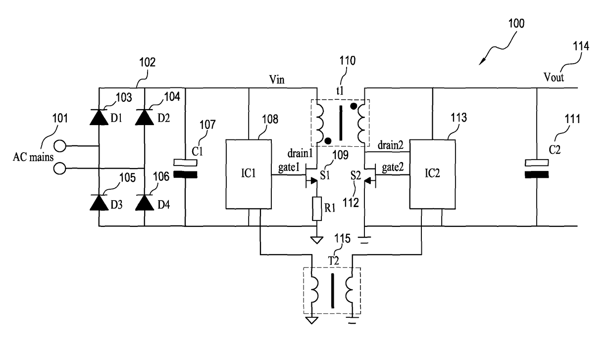
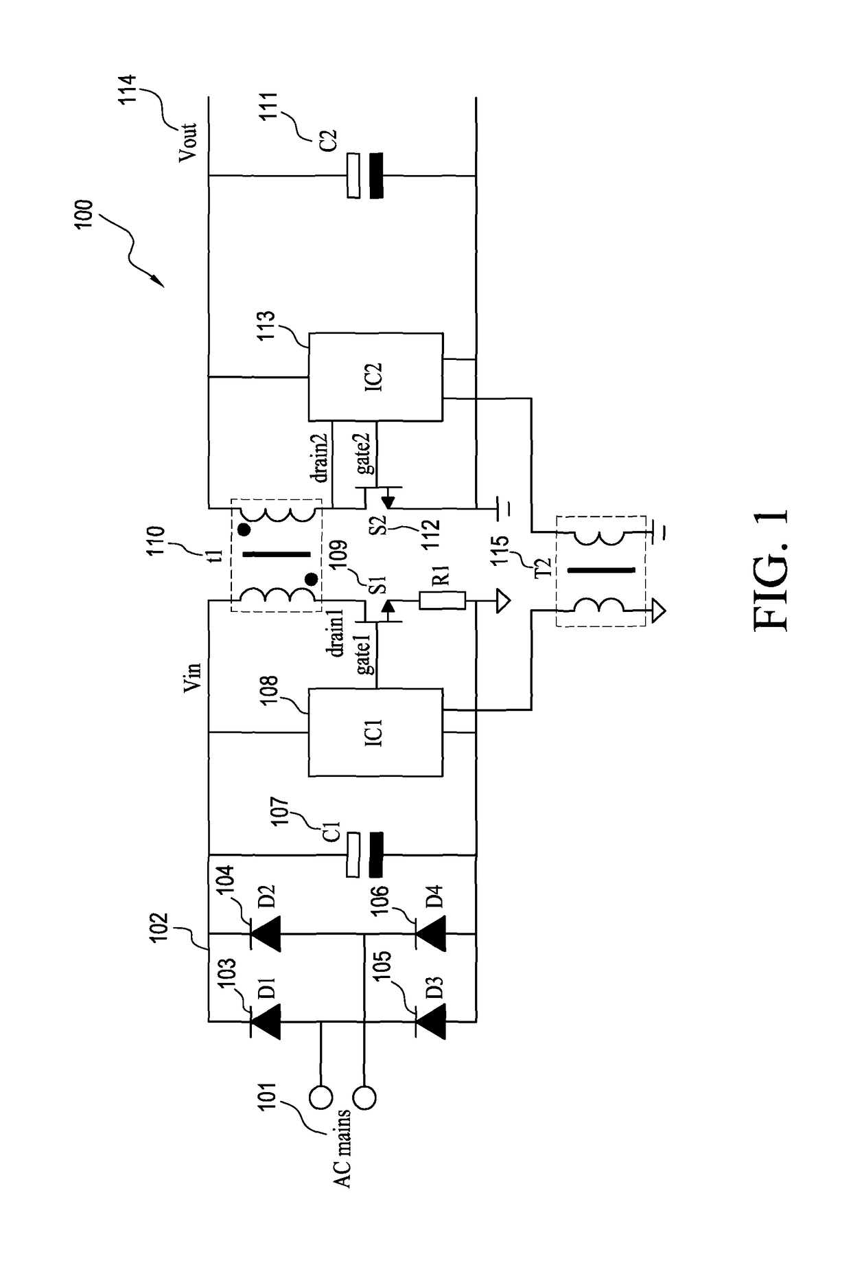
first embodiment
[0052]FIG. 7 illustrates a circuit diagram for a first embodiment;
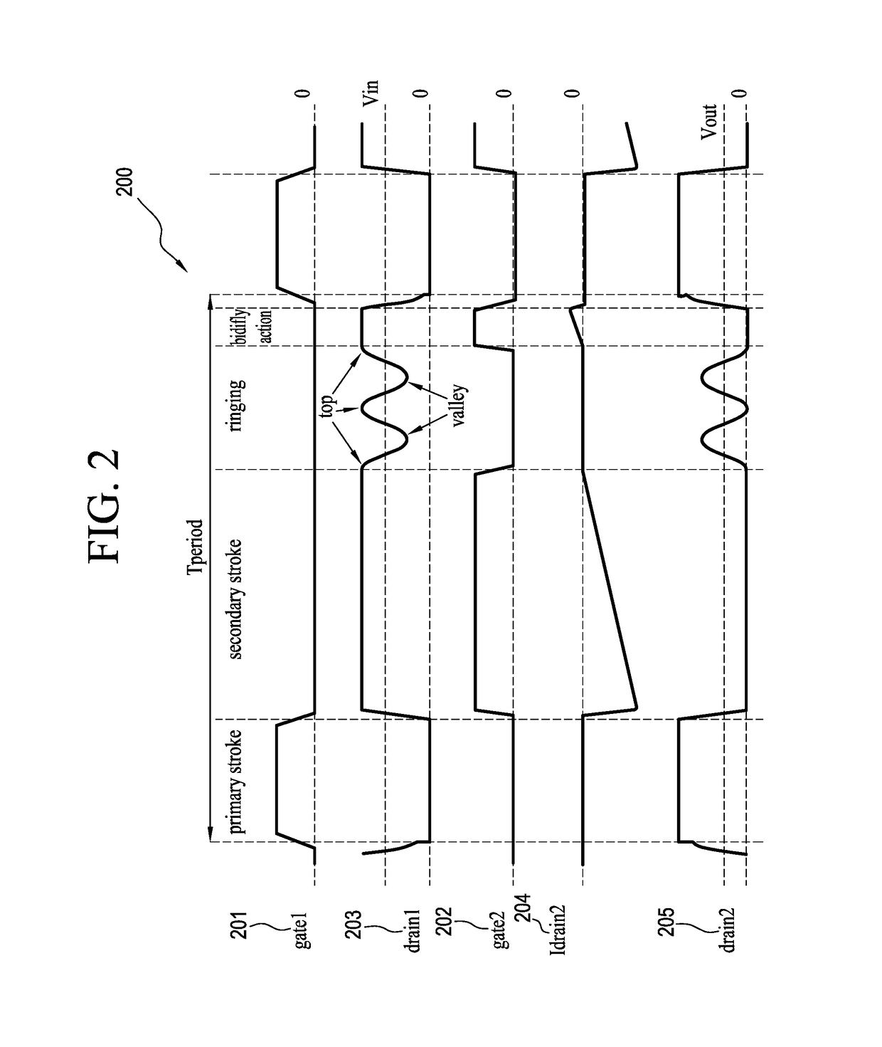
[0053]FIG. 8 illustrates a timing diagram for a first embodiment;
[0054]FIG. 9 illustrates timing diagram for bidifly action extension for a fixed frequency operation;
[0055]FIG. 10 illustrates a timing diagram for bidifly action reduction for a fixed frequency operation;
second embodiment
[0056]FIG. 11 illustrates a circuit diagram for a second embodiment;
[0057]FIG. 12 illustrates a timing diagram for bidifly action with hard switching at the secondary side;
third embodiment
[0058]FIG. 13 illustrates a circuit diagram for the third embodiment;
[0059]FIG. 14 illustrates a circuit diagram of a zero voltage switch controller;
[0060]FIG. 15 illustrates a circuit diagram for a valley and top detection circuit;
[0061]FIG. 16 illustrates a timing diagram 1600 for the valley and top detection circuit, and
[0062]FIG. 17 illustrates a method for maintaining zero voltage switching while having a fixed switching frequency.
PUM
 Abstract
Description
Claims
Application Information
 - R&D Engineer
- R&D Manager
- IP Professional
- Industry Leading Data Capabilities
- Powerful AI technology
- Patent DNA Extraction
Browse by: Latest US Patents, China's latest patents, Technical Efficacy Thesaurus, Application Domain, Technology Topic.
© 2024 PatSnap. All rights reserved.Legal|Privacy policy|Modern Slavery Act Transparency Statement|Sitemap