Switching regulator with reduced conducted emissions

a technology of conductivity and switching regulator, applied in the direction of electric variable regulation, process and machine control, instruments, etc., can solve the problems of difficult electronic devices, difficult to achieve significant margins below the requirements of cispr 22, and difficult to achieve requirements using fixed-frequency converters

a technology of conductivity and switching regulator, applied in the direction of electric variable regulation, process and machine control, instruments, etc., can solve the problems of difficult electronic devices, difficult to achieve significant margins below the requirements of cispr 22, and difficult to achieve requirements using fixed-frequency converters

US20050218873A1Inactive Publication Date: 2005-10-06ELSTER ELECTRICTY LLC

Image

  • Switching regulator with reduced conducted emissions
  • Switching regulator with reduced conducted emissions
  • Switching regulator with reduced conducted emissions

Examples


Embodiment Construction

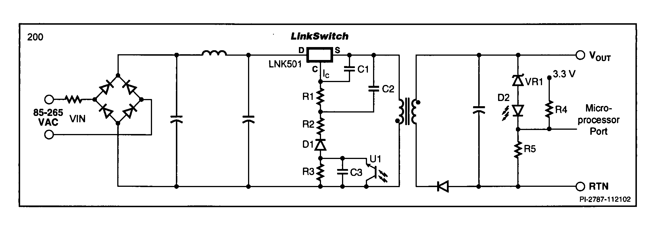
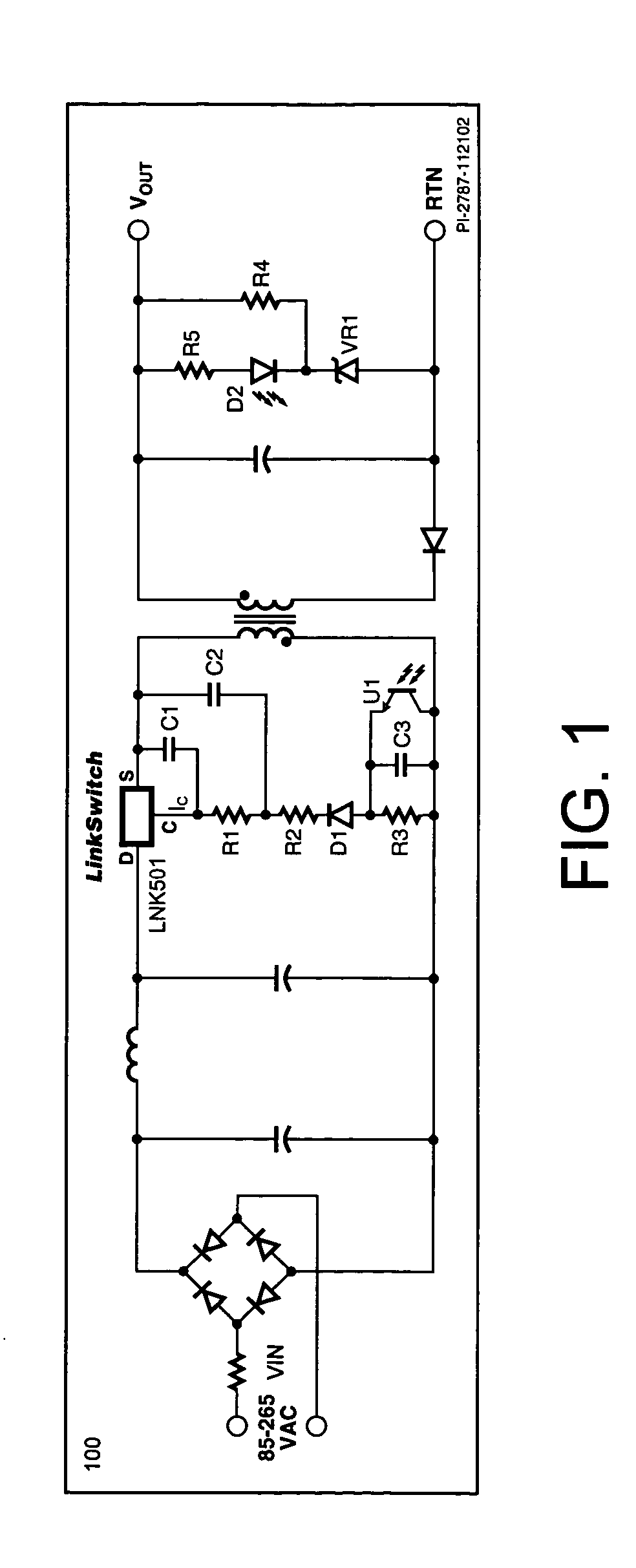
[0029] The present invention provides a method by which a low cost, fixed-frequency switching converter 1C can be utilized to provide a robust power supply while achieving an improved operating margin below CISPR 22 conducted limits. The design technique achieves improved conducted EMI margin with almost no additional hardware cost.

[0030]FIG. 3 shows the fixed-frequency power supply of FIG. 1 with a modification to the closed loop feedback system in accordance with the present invention. The modification to the feedback loop includes injecting a small noise source into the optical isolator current sensing circuit. To accomplish this, a microcontroller (not shown) develops a random output waveform on a port pin in accordance with a random number generator. This random switch pattern is used to alter the voltage in the series sensing string that includes the optical isolator by changing the voltage created by the resistor divider R4 / R5. By inserting a several millivolt signal of rand...


PUM


Abstract

A fixed-frequency switching regulator having a noise injection circuit. Noise is injected into the feedback loop of the switching regulator to modify the switching waveform to reduce individual frequency harmonics of the resultant Fourier Series. The reduced frequency harmonics allow the switching regulator to achieve reduced conducted emissions.

Description

FIELD OF THE INVENTION [0001] This invention generally relates to the field of power supplies. More particularly, this invention relates to a system and method of reducing conducted emissions in a fixed-frequency switching regulator to meet CISPR 22 requirements. BACKGROUND OF THE INVENTION [0002] Recently, the Federal Communications Commission (FCC) has imposed limits on conducted and radiated emissions from unintentional radiators to update the references to Publication 22 of the International Electrotechnical Commission (IEC), International Special Committee on Radio Interference (CISPR). It is difficult for electronic devices, such as devices that include fixed-frequency, switching power supplies to meet CISPR 22, as it requires diligence in component selection and printed circuit board layout. [0003] The operation of a conventional fixed-frequency switching regulator will now be described with FIG. 1. The switching regulator 100 utilizes a LinkSwitch integrated circuit from Pow...

Claims


Application Information

Patent Timeline
06 Oct 2005
Publication
US20050218873A1
IPC
G05F1/40; H02M1/12; H02M3/335
CPC
H02M1/12; H02M2001/0025; H02M3/33507; H02M1/44; H02M1/0025
Inventors
SHUEY, KENNETH C.; MASON, ROBERT T.