Aircraft
a technology for aircraft and aircraft, applied in the field of aircraft, can solve the problems of loss of the ability to maintain stable aircraft flight, and achieve the effects of reducing the damage to objects from contact with aircraft 10, facilitating stable flight of aircraft 10, and softening the impa
- Summary
- Abstract
- Description
- Claims
- Application Information
AI Technical Summary
Benefits of technology
Problems solved by technology
Method used
Image
Examples
embodiment 1
Aircraft Schematic Framework
[0032]Hereinafter aircraft 10 according to Embodiment 1 will be described.
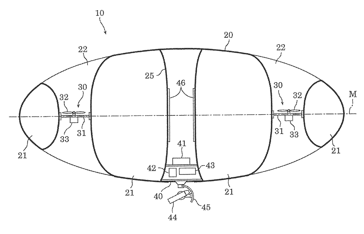
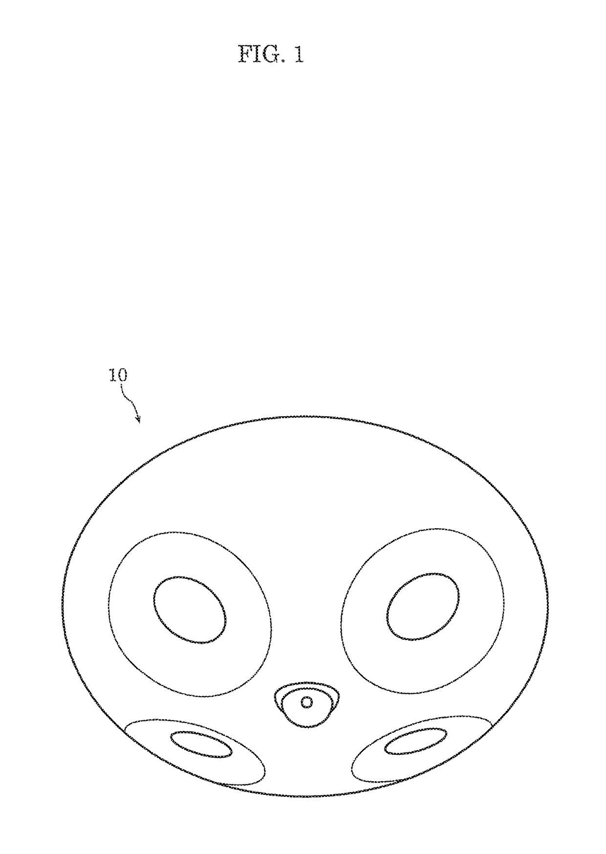
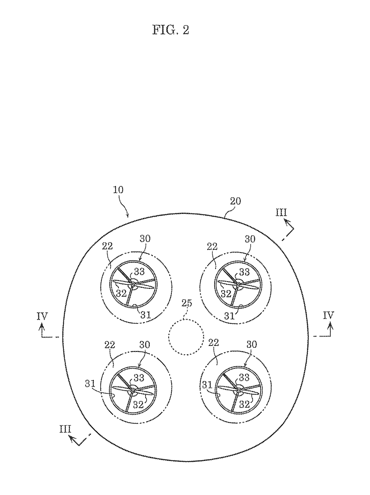
[0033]FIG. 1 is a perspective view of the bottom of the aircraft according to Embodiment 1. FIG. 2 is a plan view of the aircraft according to Embodiment 1. FIG. 3 is a cross sectional view of the aircraft taken at line III-III in FIG. 2. FIG. 4 is a cross sectional view of the aircraft taken at line IV-IV in FIG. 2.
[0034]As illustrated in FIG. 1 and FIG. 2, aircraft 10 according to Embodiment 1 includes a single balloon 20 as the shock absorber and four rotor units 30. Aircraft 10 also includes controller 41, battery 42, projector 43, and camera 44 as onboard devices, as illustrated in FIG. 3 and FIG. 4. Aircraft 10 further includes luminous body 46.
[0035]Next, balloon 20 will be described.
[0036]FIG. 5 is a plan view of the balloon according to Embodiment 1. FIG. 6 is a cross sectional view of the balloon taken at line VI-VI in FIG. 5.
[0037]As illustrated in FIG. 3, FIG. 4, ...
embodiment 2
[0105]Hereinafter aircraft 10A according to Embodiment 2 will be described. Aircraft 10A according to Embodiment 2 is achieved by equipping rudders 34 in the bottom ends of ventilation holes 22 in aircraft 10 according to Embodiment 1.
[0106]As illustrated in FIG. 7 and FIG. 8, aircraft 10A according to Embodiment 2 includes, in addition to the components included in aircraft 10 according to Embodiment 1, rudders 34 and, flow conditioning; plates 35 in ventilation holes 22 in addition to rotor units 30.
[0107]FIG. 7 is a plan view of the aircraft according to Embodiment 2. FIG. 8 is a cross sectional view of the aircraft taken at line VIII-VIII in FIG. 7.
[0108]Rudders 34 are disposed in the bottom ends of ventilation holes 22. Each rudder 34 is an elongated plate-shaped component, and in a top view of aircraft 10A, when in an unrotated reference orientation, is disposed approximately parallel to line PQ connecting central axis P of aircraft 10A and central axis Q of ventilation hole 2...
embodiment 3
[0112]Hereinafter aircraft 10B according to Embodiment 3 will be described. Aircraft 10B according to Embodiment 3 is achieved by rearranging rotor units 30 in aircraft 10 according to Embodiment 1.
[0113]FIG. 10 is a cross sectional view of the aircraft according to Embodiment 3 and corresponds to FIG. 3.
[0114]As illustrated in FIG. 10, rotor units 30 equipped in aircraft 10B according to Embodiment 3 are disposed below center plane M passing through the vertical center of balloon 20. Stated differently, the entirety of each rotor unit 30 is disposed below center plane M of balloon 20. In this way, rotor unit 30 may be disposed in each ventilation hole 22 of aircraft 10B in a region ranging from center plane M of balloon 20 to the bottom end of ventilation hole 22.
PUM
 Abstract
Description
Claims
Application Information
 - R&D
- Intellectual Property
- Life Sciences
- Materials
- Tech Scout
- Unparalleled Data Quality
- Higher Quality Content
- 60% Fewer Hallucinations
Browse by: Latest US Patents, China's latest patents, Technical Efficacy Thesaurus, Application Domain, Technology Topic, Popular Technical Reports.
© 2025 PatSnap. All rights reserved.Legal|Privacy policy|Modern Slavery Act Transparency Statement|Sitemap|About US| Contact US: help@patsnap.com


