Aircraft

a technology for aircraft and propellers, applied in the field of aircraft, can solve the problems of loss of the ability to maintain stable aircraft flight, and achieve the effects of reducing the damage to objects from contact with aircraft 10, facilitating stable flight of aircraft 10, and softening the impa

Active Publication Date: 2017-02-02
PANASONIC INTELLECTUAL PROPERTY MANAGEMENT CO LTD
View PDF3 Cites 17 Cited by
  • Summary
  • Abstract
  • Description
  • Claims
  • Application Information

AI Technical Summary

Benefits of technology

[0067]Aircraft 10 according to Embodiment 1 includes: a plurality of rotor units 30 each including propeller 32 and motor 33 that drives propeller 32; and balloon 20 as a shock absorber covering an entire vertical length of a lateral side of the plurality of rotor units 30.
[0068]With aircraft 10, since the lateral sides of rotor unit 30 are covered by balloon 20 across the entire vertical length of rotor units 30, if aircraft 10 contacts an object mid-flight, balloon 20 will contact the object instead of rotor units 30. Stated differently, even if aircraft 10 contacts an object mid-flight, contact between rotor units 30 and the object can be avoided. Thus, according to Embodiment 1, even if aircraft 10 contacts an object mid-flight, damage to rotor units 30 resulting from the contact can be prevented and stable flight of aircraft 10 can be maintained.
[0069]Moreover, if aircraft 10 were to crash into the ground, the gas-filled balloon 20 would contact the ground and deform, thereby softening the impact. As such, Embodiment 1 can prevent damage to rotor unit 30 resulting from a crash. Moreover, even if aircraft 10 were to crash into the ground, since the gas-filled balloon 20 would contact the object rather than rotor unit 30 or onboard device, damage to the object from contact with aircraft 10 can be reduced.
[0070]Moreover, spaces filled with gas such as helium are formed in balloon 20 in regions between rotor units 30 in addition to in a region surrounding all rotor units 30 disposed in predetermined locations. Thus, with Embodiment 1, sufficient inner volumetric capacity can be secured in balloon 20, thereby reducing the need to increase the size of balloon 20.
[0071]Moreover, when aircraft 10 includes a plurality of rotor units 30, in order to stabilize flight of aircraft 10, the plurality of rotor units 30 are preferably spaced apart by a given distance. However, as described above, gas chambers filled with gas such as helium are also provided in regions between rotor units 30 with balloon 20 according to Embodiment 1. Thus, according to Embodiment 1, a sufficient gas chamber capacity can be secured without enlarging aircraft. 10, and sufficient distance between rotor units 30 can be secured. This makes it possible to stabilize flight of aircraft 10.
[0072]Moreover, in Embodiment 1, aircraft 10 flies using both the buoyant force of the gas filling balloon 20 and the buoyant force of air current generated by rotor units 30. As such, compared to when just the buoyant force resulting from rotor units 30 running is used, energy such as power needed to drive rotor units 30 can be saved, thereby increasing the flight time aircraft 10 is capable of.

Problems solved by technology

Thus, when these aircrafts contact an object mid-flight, parts necessary to achieve flight such as rotor units and fins may be damaged, which may result in loss of ability to maintain stable aircraft flight.

Method used


Image

  • Aircraft
  • Aircraft
  • Aircraft

Examples


embodiment 1

Aircraft Schematic Framework

[0032]Hereinafter aircraft 10 according to Embodiment 1 will be described.

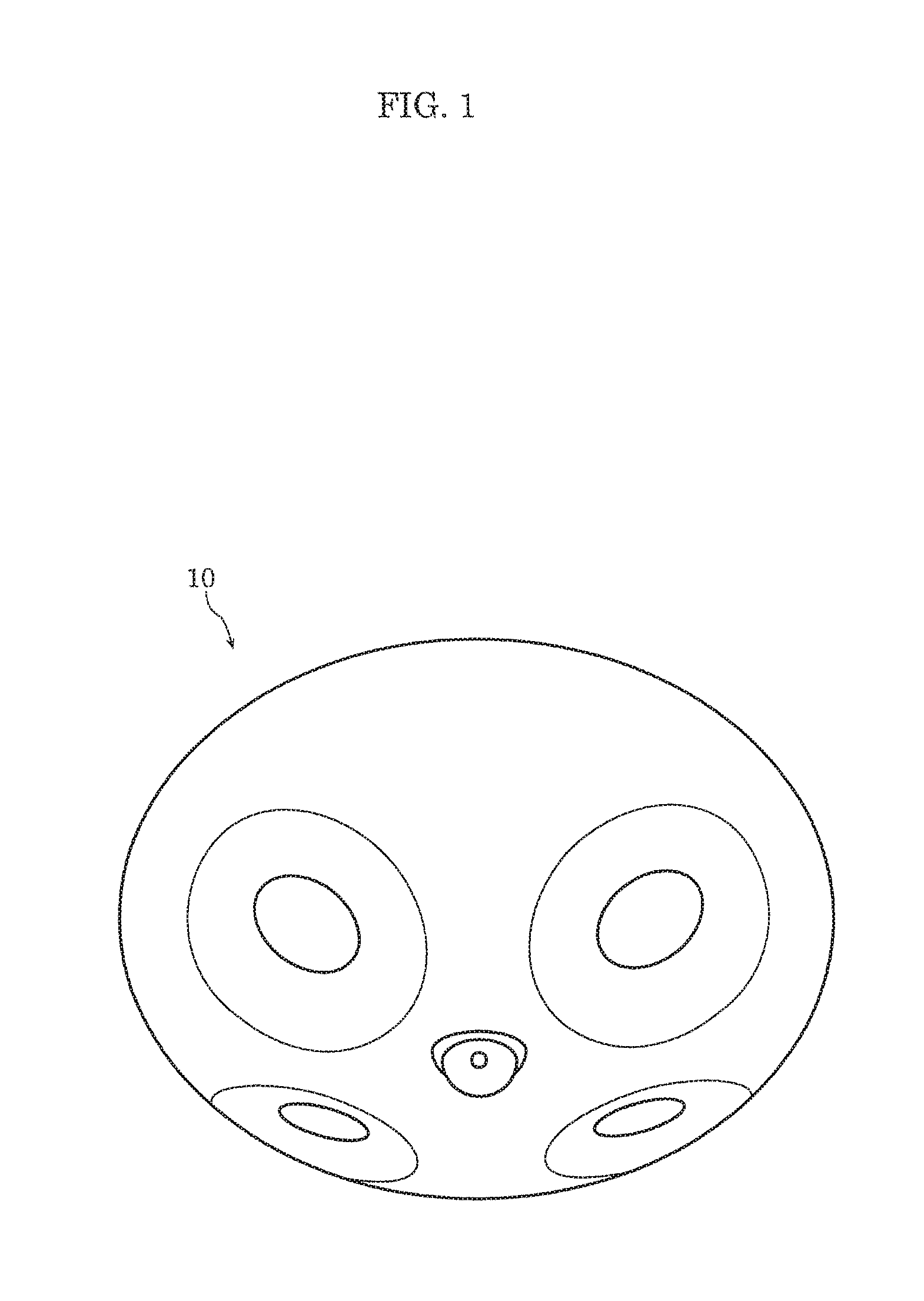
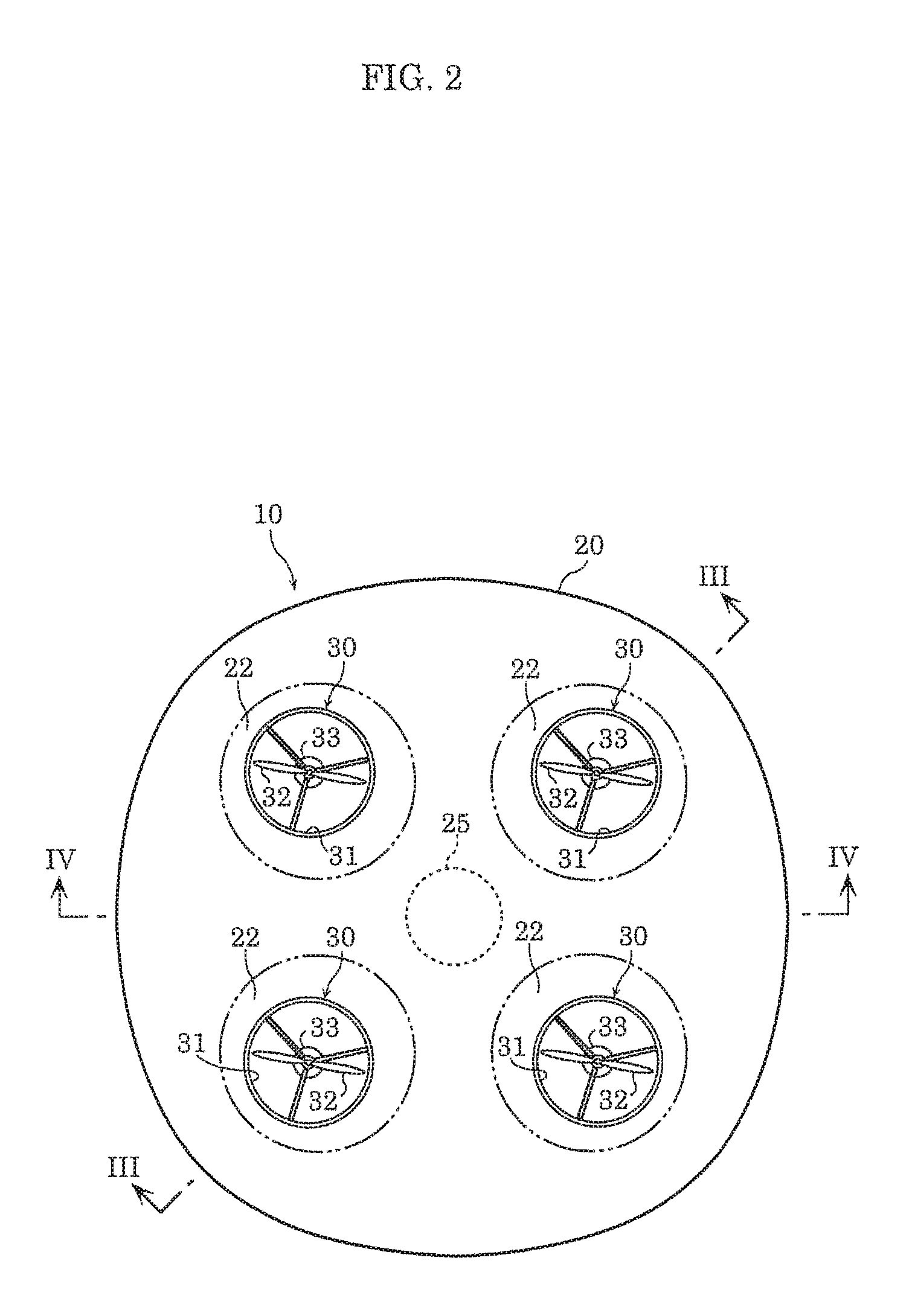
[0033]FIG. 1 is a perspective view of the bottom of the aircraft according to Embodiment 1. FIG. 2 is a plan view of the aircraft according to Embodiment 1. FIG. 3 is a cross sectional view of the aircraft taken at line III-III in FIG. 2. FIG. 4 is a cross sectional view of the aircraft taken at line IV-IV in FIG. 2.

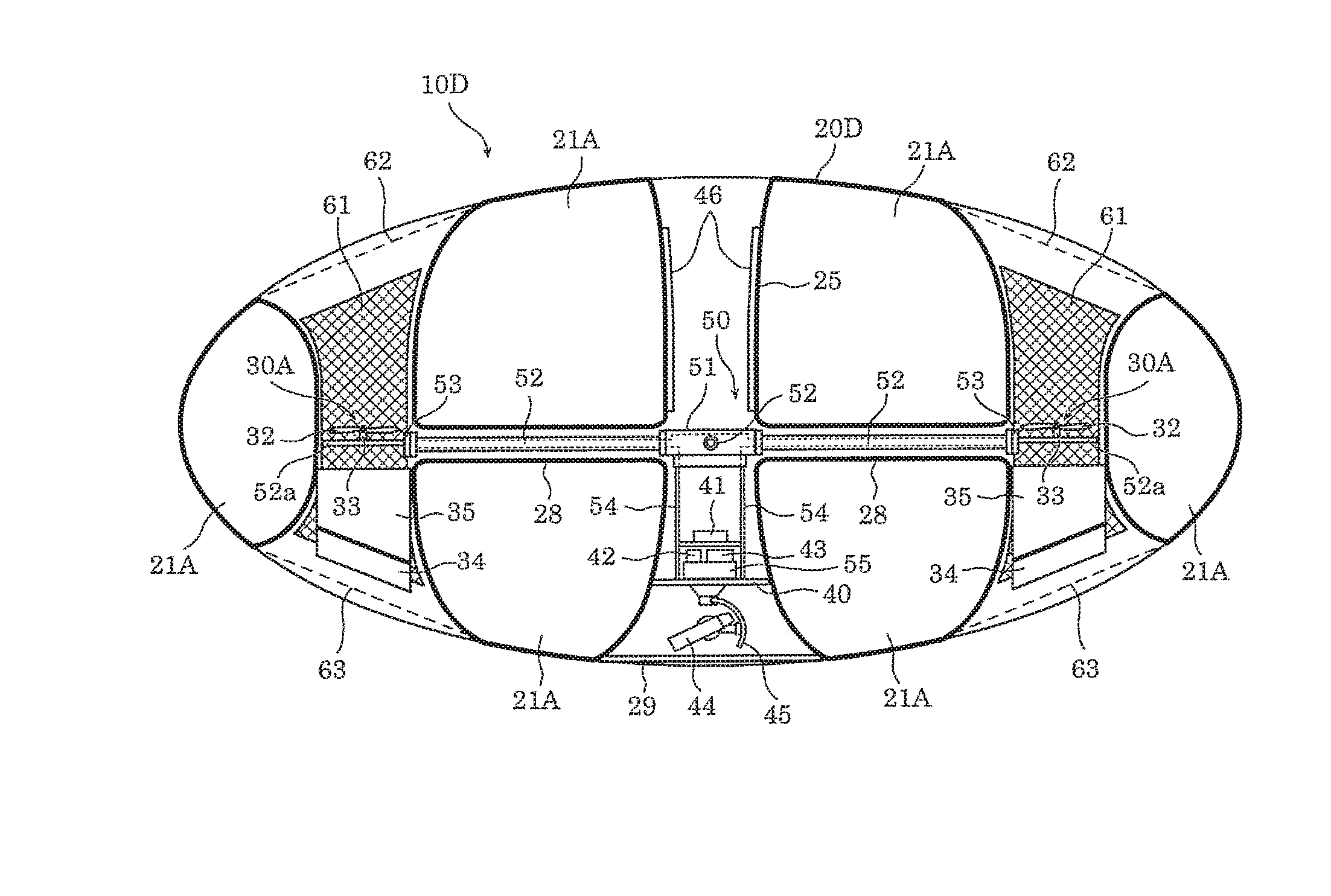
[0034]As illustrated in FIG. 1 and FIG. 2, aircraft 10 according to Embodiment 1 includes a single balloon 20 as the shock absorber and four rotor units 30. Aircraft 10 also includes controller 41, battery 42, projector 43, and camera 44 as onboard devices, as illustrated in FIG. 3 and FIG. 4. Aircraft 10 further includes luminous body 46.

Balloon

[0035]Next, balloon 20 will be described.

[0036]FIG. 5 is a plan view of the balloon according to Embodiment 1. FIG. 6 is a cross sectional view of the balloon taken at line VI-VI in FIG. 5.

[0037]As illustrated in FIG. 3, FIG. 4, ...

embodiment 2

[0105]Hereinafter aircraft 10A according to Embodiment 2 will be described. Aircraft 10A according to Embodiment 2 is achieved by equipping rudders 34 in the bottom ends of ventilation holes 22 in aircraft 10 according to Embodiment 1.

[0106]As illustrated in FIG. 7 and FIG. 8, aircraft 10A according to Embodiment 2 includes, in addition to the components included in aircraft 10 according to Embodiment 1, rudders 34 and, flow conditioning; plates 35 in ventilation holes 22 in addition to rotor units 30.

[0107]7 is a plan view of the aircraft according to Embodiment 2. FIG. 8 is a cross sectional view of the aircraft taken at line in FIG. 7.

[0108]Rudders 34 are disposed in the bottom ends of ventilation holes 22. Each rudder 34 is an elongated plate-shaped component, and in a top view of aircraft 10A, when in an unrotated reference orientation, is disposed approximately parallel to line PQ connecting central axis P of aircraft 10A and central axis Q of ventilation hole 22 in which rudd...

embodiment 3

[0112]Hereinafter aircraft 10B according to Embodiment 3 will be described. Aircraft 10B according to Embodiment 3 is achieved by rearranging rotor units 30 in aircraft 10 according to Embodiment 1.

[0113]FIG. 10 is a cross sectional view of the aircraft according to Embodiment 3 and corresponds to FIG. 3.

[0114]As illustrated in FIG. 10, rotor units 30 equipped in aircraft 10B according to Embodiment 3 are disposed below center plane M passing through the vertical center of balloon 20. Stated differently, the entirety of each rotor unit 30 is disposed below center plane M of balloon 20. In this way, rotor unit 30 may be disposed in each ventilation hole 22 of aircraft 10B in a region ranging from center plane M of balloon 20 to the bottom end of ventilation hole 22.


PUM


Abstract

An aircraft includes: a plurality of rotor units each including a propeller and a motor that drives the propeller; and a shock absorber covering the entire vertical length of lateral sides of the plurality of rotor units.

Description

CROSS REFERENCE TO RELATED APPLICATIONS[0001]The present application is based on and claims priority of Japanese Patent Application No. 2015-152301 filed on Jul. 31, 2015, Japanese Patent Application No. 2015-173373 filed on Sep. 3, 2015, and Japanese Patent Application No. 2016-016117 filed on Jan. 29, 2016. The entire disclosures of the above-identified applications, including the specifications, drawings and claims are incorporated herein by reference in their entirety.BACKGROUND[0002]1. Field[0003]The present disclosure relates to an aircraft including a plurality of rotor units.[0004]2. Description of the Related Art[0005]Japanese Unexamined Patent Application Publication No. 2011-046355 discloses an aircraft, including a plurality of rotor units each including a propeller. This type of aircraft is known as a multicopter or drone.[0006]Japanese Unexamined Patent Application Publication No. 04-022386 discloses an aircraft including a buoyant body filled with helium gas and a sin...

Claims


Application Information

Patent Timeline
Patent Type & Authority Applications(United States)
IPC IPC(8): B64C27/00B64C27/04B64B1/58
CPCB64C27/006B64B2201/00B64C27/04B64B1/58B64B1/14B64B1/26B64B1/40B64C27/20B64C39/024B64D47/04B64D47/08B64D2203/00B64U10/30B64U10/13B64U30/20B64U50/19B64U2101/30
Inventor MATSUMOTO, HIROYUKIICHIMURA, SHIGENORIIYOBE, TATSUYATAKITA, MIZUKI
Owner PANASONIC INTELLECTUAL PROPERTY MANAGEMENT CO LTD
Why Eureka
Try Eureka