Actuator assembly for conducting partial stroke testing

a technology of partial stroke and actuator assembly, which is applied in the direction of friction gearing, gearing, servomotor, etc., can solve the problems of insufficient testing of the shut-off valve itself, undesirable disruption of the process, and dangerous conditions, and achieve the effect of eliminating spurious valve travel

Active Publication Date: 2018-11-20
QTRCO
View PDF8 Cites 1 Cited by
  • Summary
  • Abstract
  • Description
  • Claims
  • Application Information

AI Technical Summary

Benefits of technology

[0011]In one aspect the present invention provides a valve actuator assembly which can be used for PST and which eliminates spurious valve travel.
[0012]In another aspect the present inventions provides a valve actuator assembly which can be used for PST and which eliminates false failures.

Problems solved by technology

As the shutdown valves are operated infrequently, there is a high possibility that they will stick or freeze when the shutdown operation is required, thus resulting in a dangerous condition if an emergency shutdown has been requested.
However, such systems may not provide for the testing of shut-off valves themselves, other than full stroking the valve.
However, the problem with full stroking or completely closing the valve is that it causes an undesirable disruption in the process.
However, they suffer from several disadvantages in that they require extensive operator training and procedures both for engagement and disengagement operations.
Furthermore, they typically cannot be immediately disengaged should an ESD occur during partial stroke testing.
This severely compromises safety.
However, as only a small percentage of the air pressure can be released, the available torque or force output from the actuator is only a very small percentage of the actuator rated torque or force.
In this situation, additional air must be released to develop sufficient actuator output, however, at the resulting pressure the actuator will cause excessive (spurious) valve travel and a resultant process disruption.
Thus the user has what is called a false failure whereby maintenance must be performed to determine the cause of the failure.
Too often nothing is found other than a slight resistance to valve motion.
As the process must be shut down for this maintenance action, the PST system causes the very process disruption that it was designed to prevent.

Method used


Image

  • Actuator assembly for conducting partial stroke testing
  • Actuator assembly for conducting partial stroke testing
  • Actuator assembly for conducting partial stroke testing

Examples


Embodiment Construction

[0026]As used herein, the terms “connected,”“interconnected,” and “operatively connected,” include direct or indirect connection between first and second components, e.g., there may be one or more other components between the first and second component.

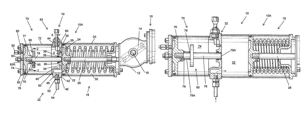
[0027]The actuator assembly of the present invention can be used with respect to scotch yoke assemblies, rack and pinion assemblies, and linear actuators. With respect to scotch yoke assemblies, U.S. Pat. No. 8,087,316 ('316 patent) and U.S. Pat. No. 8,863,596 ('596 patent), both of which are incorporated herein by reference for all purposes, disclose double acting scotch yoke actuators as set forth in the '316 patent and single acting scotch yoke actuators as set forth in the '596 patent. With respect to rack and pinion type actuators, a double-acting rack and pinion actuator assembly is disclosed in U.S. Pat. No. 5,492,050 ('050 patent) which is incorporated herein by reference for all purposes.

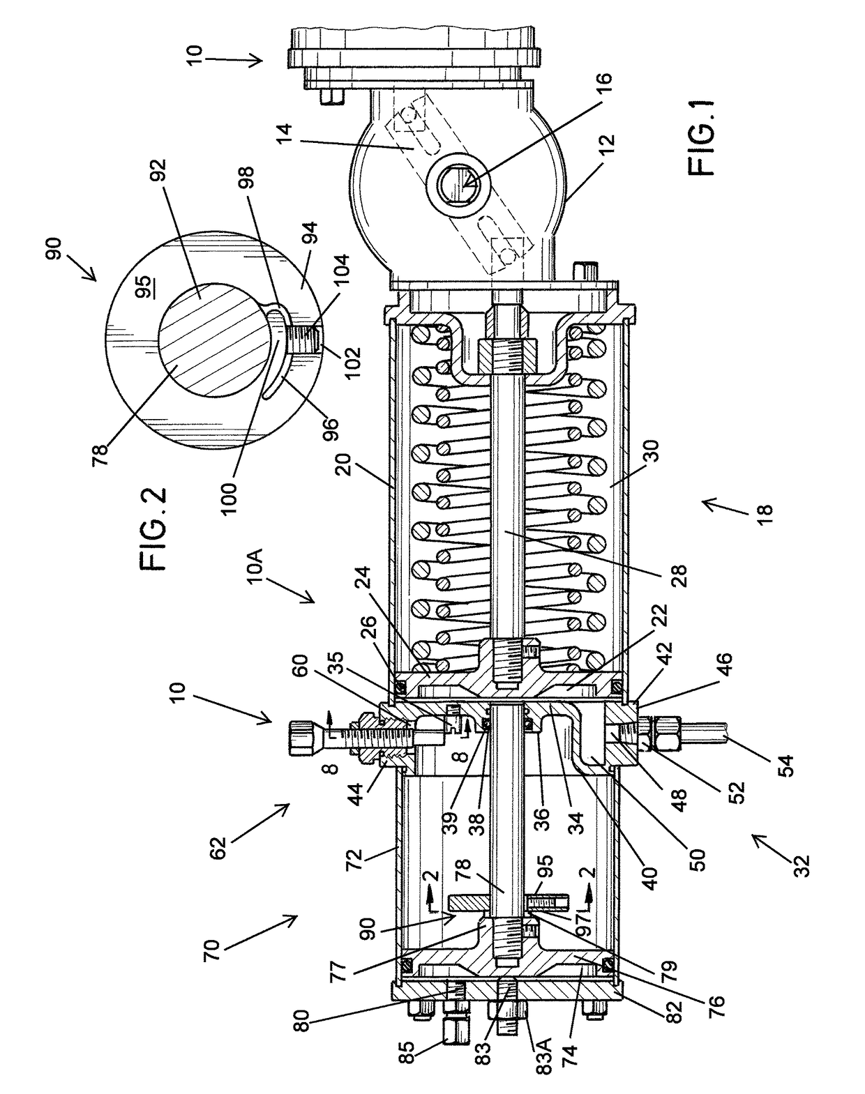
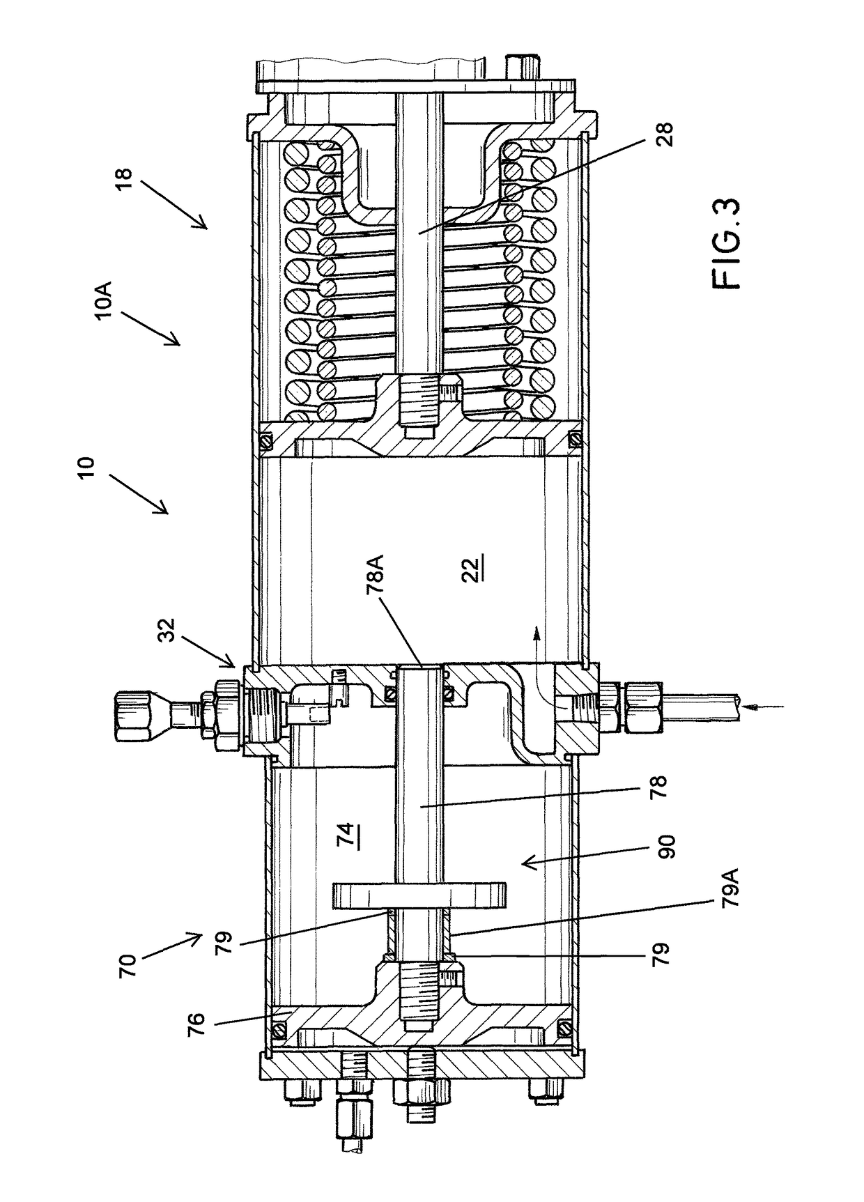
[0028]Referring first to FIG. 1, the a...


PUM


Abstract

A modular actuator assembly which can be used for partial stroke testing of a valve, the assembly having a force module and a tandem piston module. The force module has a primary piston and piston rod interconnected to a shaft which is movably mounted therein. The tandem piston module is connected to the force module and has a tandem piston and piston rod. An indicator plate is connected to the piston rod and is selectively positionable on the tandem piston rod. The tandem piston rod extends into the force module and acts as a pneumatically engaged hard stop for preventing spurious travel of the primary piston and hence spurious valve travel.

Description

FIELD OF THE INVENTION[0001]The present invention relates to a partial stroke testing system and, more particularly, to a partial stroke testing system for the online testing of an emergency shut off valve.BACKGROUND OF THE INVENTION[0002]In the oil, gas, petroleum, and power industries, emergency shutdown of a process must be provided for under certain fault conditions.[0003]An emergency shutdown (ESD) system is usually implemented by pneumatically controlled shut off valves, which generally remain open while the process is operating safely. These valves are usually only closed when an emergency shut down is required, or for maintenance. Often, processes operate for long periods of time, e.g., years, without shutting down. As the shutdown valves are operated infrequently, there is a high possibility that they will stick or freeze when the shutdown operation is required, thus resulting in a dangerous condition if an emergency shutdown has been requested.[0004]The problem can be exac...

Claims


Application Information

Patent Timeline
Patent Type & Authority Patents(United States)
IPC IPC(8): F15B15/14F15B11/12F15B15/28F16H19/04F15B19/00F15B15/06
CPCF15B15/2815F15B11/123F15B15/1409F15B15/065F16H19/04F15B15/2807F15B19/005F15B2211/7107F15B15/066
Inventor HOLTGRAVER, EDWARD G.HOWARD, JAMES R.
Owner QTRCO
Why Eureka
Try Eureka