Supercharge Your Innovation With Domain-Expert AI Agents!

Single suction centrifugal blower

a centrifugal fan and single suction technology, applied in the direction of machines/engines, mechanical equipment, liquid fuel engines, etc., can solve the problems of difficult processing of the fixing side plate of the complex motor 108, and the technique described in the patent literature 1 is not easily applied, so as to suppress the effect of the decrease in performan

Active Publication Date: 2018-11-27
PANASONIC INTELLECTUAL PROPERTY MANAGEMENT CO LTD
View PDF26 Cites 0 Cited by
  • Summary
  • Abstract
  • Description
  • Claims
  • Application Information

AI Technical Summary

Benefits of technology

This approach enables the downsizing of the centrifugal fan casing without compromising static pressure performance, reduces turbulence and pressure losses, and simplifies the processing of the motor fixing side plate, ensuring effective air flow conversion from dynamic to static pressure.

Problems solved by technology

Such complicated shape motor fixing side plate 108 is not easily processed.
However, in a case where an internal static pressure in particular is set to be high in single suction type centrifugal fan 101 and there is a need for forming casing 102 from a steel plate for ensuring strength of casing 102, the technique described in Patent Literature 1 is not easily applied.

Method used


Image

  • Single suction centrifugal blower
  • Single suction centrifugal blower
  • Single suction centrifugal blower

Examples


first exemplary embodiment

[0023](First Exemplary Embodiment)

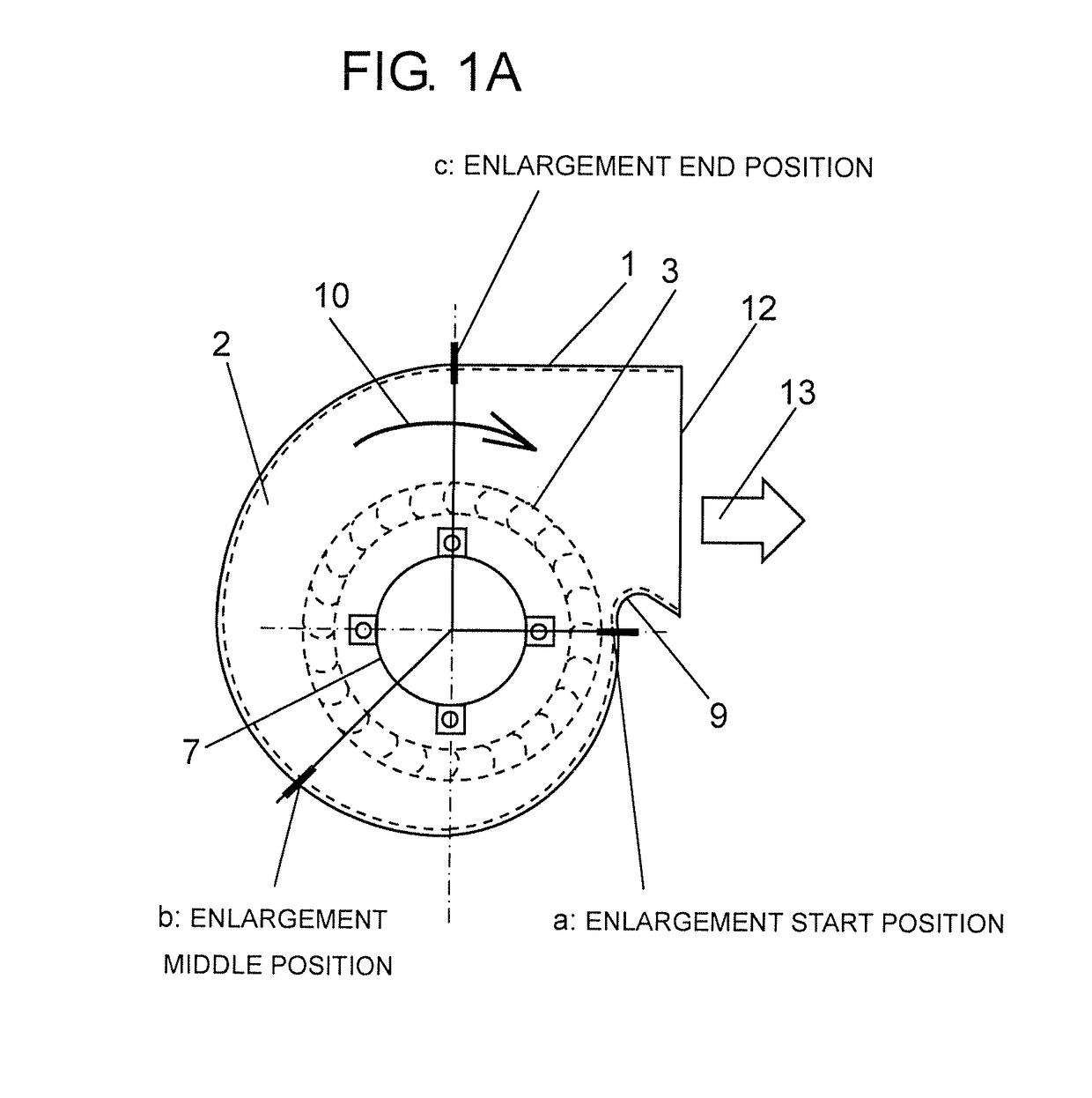
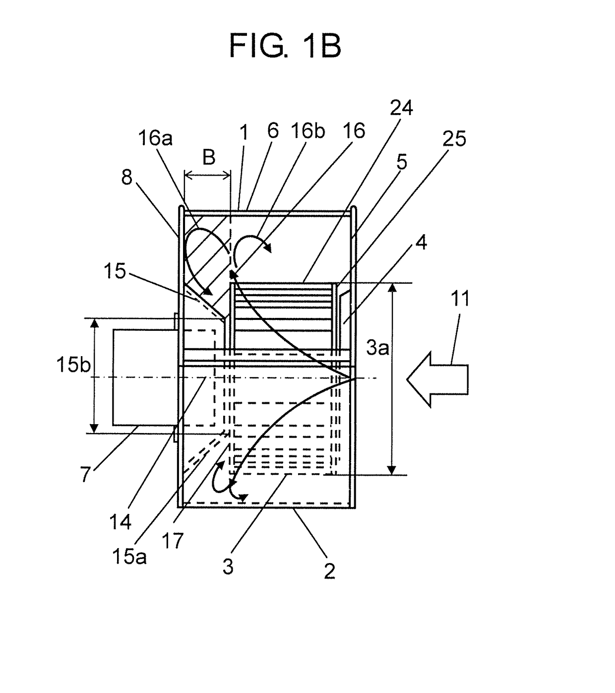
[0024]FIG. 1A is a side view of a single suction type centrifugal fan of a first exemplary embodiment of the present invention, and FIG. 1B is a front view of the same single suction type centrifugal fan. As shown in FIGS. 1A and 1B, single suction type centrifugal fan 1 includes casing 2, impeller 3 built in casing 2, the impeller having a plurality of blades 24, and main plate 17 disposed between motor 7 and impeller 3 and fixed to rotation shaft 14 of motor 7. Casing 2 includes side plate 5 including suction port 4, scroll 6, and motor fixing side plate 8 to which motor 7 is fixed. Casing 2 is formed in a spiral shape in which an area of a flow passage cross section is gradually enlarged from tongue portion 9 toward rotating direction 10 of impeller 3. Impeller 3 is fixed to motor 7.

[0025]Impeller 3 includes main plate 17, plural pieces of blades 24, and auxiliary ring 25. The plural pieces of blades 24 are arranged on an outer peripheral side of...

second exemplary embodiment

[0045](Second Exemplary Embodiment)

[0046]In a second exemplary embodiment of the present invention, the same constituent elements as those in the first exemplary embodiment will be given the same reference marks, detailed description of the constituent elements will be omitted, and only different points will be described. FIG. 4A is a side view of a single suction type centrifugal fan of the second exemplary embodiment of the present invention, and FIG. 4B is a front view of the same single suction type centrifugal fan.

[0047]As shown in FIGS. 4A and 4B, in single suction type centrifugal fan 1, several circular openings 21 are provided in main plate 17 of impeller 3. Openings 21 are provided within an area confined by first rectifying plate diameter 15b when rectifying plate 15 is projected onto main plate 17 along rotation shaft 14. Rectifying plate 15 located closer to impeller 3 is an opening end. That is, in rectifying plate 15 on the side of impeller 3, an interior of rectifyin...


PUM


Abstract

A single suction type centrifugal fan includes a casing, an impeller, and a main plate. The casing includes a side plate and a motor fixing side plate, and the side plate and the motor fixing side plate are arranged in parallel. A rectifying plate is provided between the motor fixing side plate and the main plate, and the rectifying plate is formed from an inclined surface in which an area of a cross section orthogonal to a rotation shaft is reduced toward the impeller around the rotation shaft of a motor. A first rectifying plate diameter at another side of the rectifying plate closer to the impeller is smaller than an impeller diameter of the impeller.

Description

RELATED APPLICATIONS[0001]This application is the U.S. National Phase under 35 U.S.C. § 371 of International Application No. PCT / JP2014 / 000813, filed on Feb. 18, 2014 which in turn claims the benefit of Japanese Patent Application No. 2013-057618 filed on Mar. 21, 2013, the disclosures of which applications are incorporated by reference herein.TECHNICAL FIELD[0002]The present invention relates to a single suction type centrifugal fan.BACKGROUND ART[0003]In a single suction type centrifugal fan including a scroll casing, an area of a flow passage cross section is gradually enlarged in a radial direction of an impeller from a tongue portion toward a rotating direction of the impeller. With a gas blown out from the impeller, a dynamic pressure is converted into a static pressure in the casing. In such a single suction type centrifugal fan, for downsizing of the casing, an enlargement direction of the area of the flow passage cross section is not the radial direction of the impeller but...

Claims


Application Information

Patent Timeline
Patent Type & Authority Patents(United States)
IPC IPC(8): F04D17/16F04D25/08F04D29/66F04D29/44F04D29/42
CPCF04D17/16F04D25/082F04D29/441F04D29/667F04D29/4226F04D29/422F04D29/4233F05D2250/52F05D2250/70
Inventor UEHARA, AKIMASAOUSAKA, SATOSHI
Owner PANASONIC INTELLECTUAL PROPERTY MANAGEMENT CO LTD
Features
  • R&D
  • Intellectual Property
  • Life Sciences
  • Materials
  • Tech Scout
  • Unparalleled Data Quality
  • Higher Quality Content
  • 60% Fewer Hallucinations
Learn More