Direct drive motor-based walking beam pumping unit

a technology of pumping unit and direct drive motor, which is applied in the direction of machines/engines, positive displacement liquid engines, borehole/well accessories, etc., can solve the problems of increasing failure rate, unit is not energy saving, and small change of output, so as to reduce the failure rate of pumping unit and increase the torque to work

Inactive Publication Date: 2018-12-11
LIU KUNMING
View PDF10 Cites 0 Cited by
  • Summary
  • Abstract
  • Description
  • Claims
  • Application Information

AI Technical Summary

Benefits of technology

[0011]In some embodiments, a controller controls a direct drive motor and drives a crank through the direct drive motor; the crank is connected to a beam shaft through a connecting rod and a beam; the beam shaft is connected to a balance weight; with the function of balancing according to the lever principle, the balance weight increases the torque to work. With a simple structure, the Invention cancels the combination of belt, belt pulley and reducer conventionally used in the pumping units, greatly lowering the failure rate of the pumping unit, decreasing the frequency of maintenance and service, reducing the cost in use and improving the production efficiency. Moreover, the direct drive motor-based walking beam pumping unit consumes less power; with a new variable frequency controller, the current and voltage of the motor can be adjusted based on the working condition of the pumping unit, and the output power of the motor is automatically adjusted, achieving the goal of energy saving. When the horsehead is lifted, the direct drive motor works, when the horsehead goes down, the dead load of the horsehead drives the direct drive motor to rotate to generate power in a reversed way which may save over 20% of energy and even more if the generated power can be collected and used. According to the lever principle, the balance weight arranged at a second end of the walking beam away from the horsehead increases the torque, making the direct drive motor consume less power for the same work and thus save more than 2% of energy.

Problems solved by technology

However, the lubricating oil and the drive belt of the reducer need to be replaced regularly and both the reducer and the drive belt will increase failure rate; moreover, the conventional pumping unit is not energy saving with high motor power, small change of output power and largely increased production cost.

Method used


Image

  • Direct drive motor-based walking beam pumping unit

Examples


Embodiment Construction

[0015]A clear and full description of the technical schemes of the embodiments of the Invention will be given in combination of the drawings of the embodiments of the Invention as follows. Obviously, the described embodiments are just a part rather than the whole of the embodiments of the Invention.

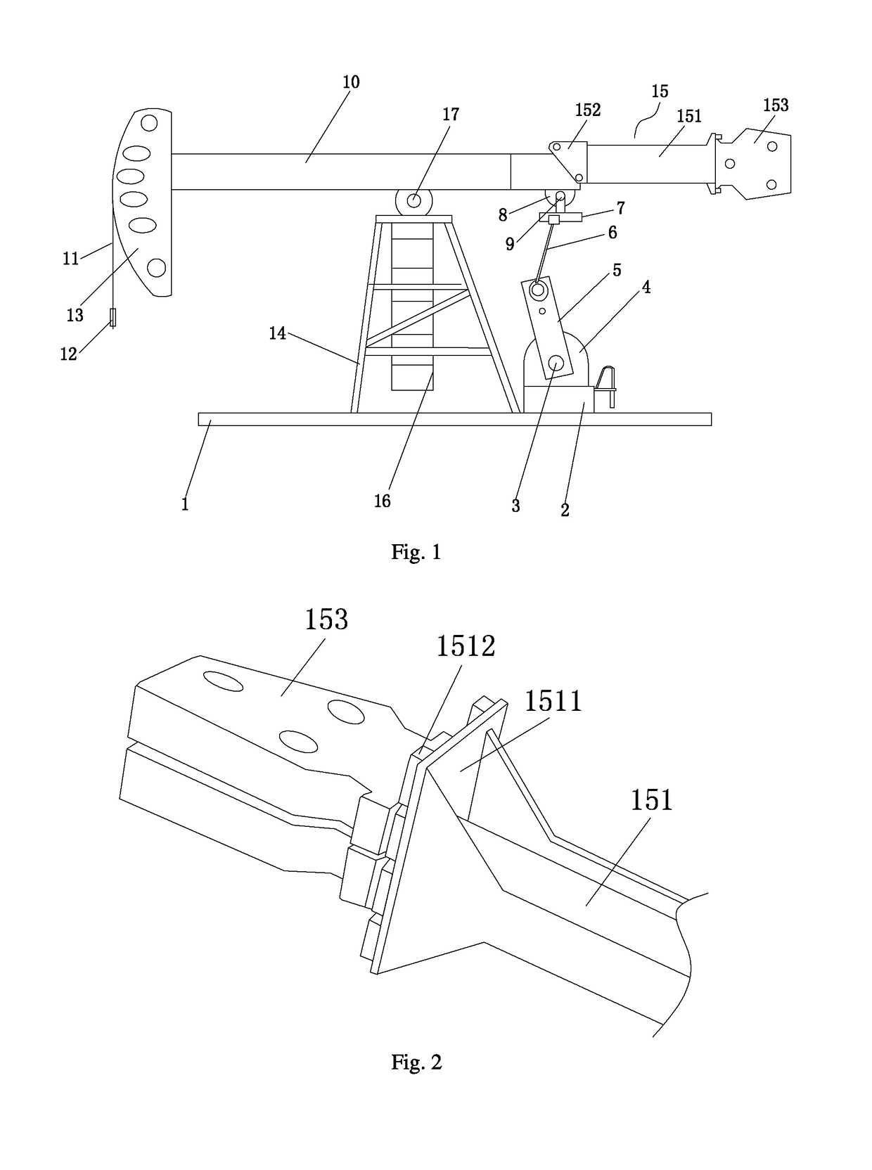
[0016]Refer to FIGS. 1 and 2, a direct drive motor-based walking-beam pumping unit, comprising a base 1, a support 14 is arranged at the upper end of the base 1; the support 14 is fixed on the base 1 through locking screws, increasing the stability of the pumping unit; a walking beam is arranged at the upper end of the support 14 and the support 14 is rotationally connected to the walking beam 10 through a support shaft 17, facilitating the walking beam 10 to rotate for operation. A horsehead 13 is arranged at a first end of the walking beam 10; a lifting rope 11 is arranged on the horsehead 13 and a beam hanger 12 is arranged on the lifting rope 11; A balance weight 15 is arranged at a s...


PUM


Abstract

A direct drive motor-based walking beam pumping unit includes a base; a support is arranged at the upper end of the base; a walking beam is arranged at the upper end of the support; a horsehead is arranged at a first of the walking beam; a lifting rope is arranged on the horsehead and a beam hanger is arranged on the lifting rope; a balance weight is arranged at a second end of the walking beam away from the horsehead; a barrel is arranged at the upper end of the base; a direct drive motor is arranged at the upper end of the barrel.

Description

CROSS-REFERENCE TO RELATED APPLICATIONS[0001]This present application claims the benefit of Chinese Patent Application No. 201610529916.5 filed on Jul. 7, 2016, the contents of which are hereby incorporated by reference.FIELD OF THE INVENTION[0002]The Invention relates to the field of pumping unit technology, particularly to a direct drive motor-based walking beam pumping unit.BACKGROUND OF THE INVENTION[0003]The pumping unit, also known as a “kowtow machine”, is a type of mechanical equipment for oil mining, which pumps oil from the well by pressure. The conventional walking beam pumping unit is powered by the cooperation of a motor and a reducer. However, the lubricating oil and the drive belt of the reducer need to be replaced regularly and both the reducer and the drive belt will increase failure rate; moreover, the conventional pumping unit is not energy saving with high motor power, small change of output power and largely increased production cost.SUMMARY OF THE INVENTION[000...

Claims


Application Information

Patent Timeline
Patent Type & Authority Patents(United States)
IPC IPC(8): E21B43/12
CPCE21B43/127E21B2043/125F03G3/06F04B47/02F04B47/14
Inventor LIU, KUNMING
Owner LIU KUNMING
Why Eureka
Try Eureka