Lighting apparatus with lens having safety light-dispersing structures

a technology of safety light and light-dispersing structure, which is applied in the field of laser light-dispersing apparatuses, can solve the problems of inability to perform the function of emergency backup light, and the inability of emergency backup light-dispersing material to function, and achieve the effect of enhancing the safety of lighting apparatus and large structur

Active Publication Date: 2018-12-11
PANASONIC INTELLECTUAL PROPERTY MANAGEMENT CO LTD
View PDF22 Cites 0 Cited by
  • Summary
  • Abstract
  • Description
  • Claims
  • Application Information

AI Technical Summary

Benefits of technology

[0008]In view of this, the present disclosure provides a lighting apparatus capable of enhancing safety for human eyes while being a lighting apparatus having laser light as a light source.
[0010]According to the lighting apparatus according to an aspect of the present disclosure, the light-dispersing structure which disperses the laser light is provided integrally in the lens which is a comparatively large structure, and thus the possibility of the light-dispersing structure falling off from the optical axis of the laser light can be reduced and the safety of the lighting apparatus can be enhanced.

Problems solved by technology

However, in the case where the light-dispersing material is attached to the light-emitting component as in the conventional technique, the light-dispersing material would also fall off together with the falling off of the light-emitting component, and thus the light-dispersing material does not function as an emergency backup.
Furthermore, in the case where the light-dispersing material is attached to another place, the light-dispersing material may fall off ahead of the light-emitting component and thus be unable to perform its function.

Method used


Image

  • Lighting apparatus with lens having safety light-dispersing structures
  • Lighting apparatus with lens having safety light-dispersing structures
  • Lighting apparatus with lens having safety light-dispersing structures

Examples


embodiment

[0028]An embodiment is described below.

[0029][Configuration of Lighting Apparatus]

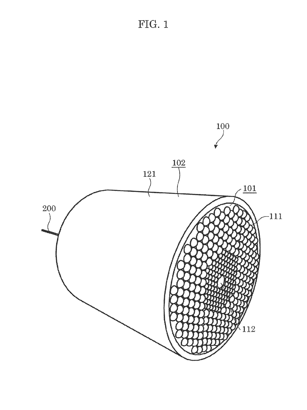
[0030]FIG. 1 is a perspective view illustrating an external appearance of a lighting apparatus.

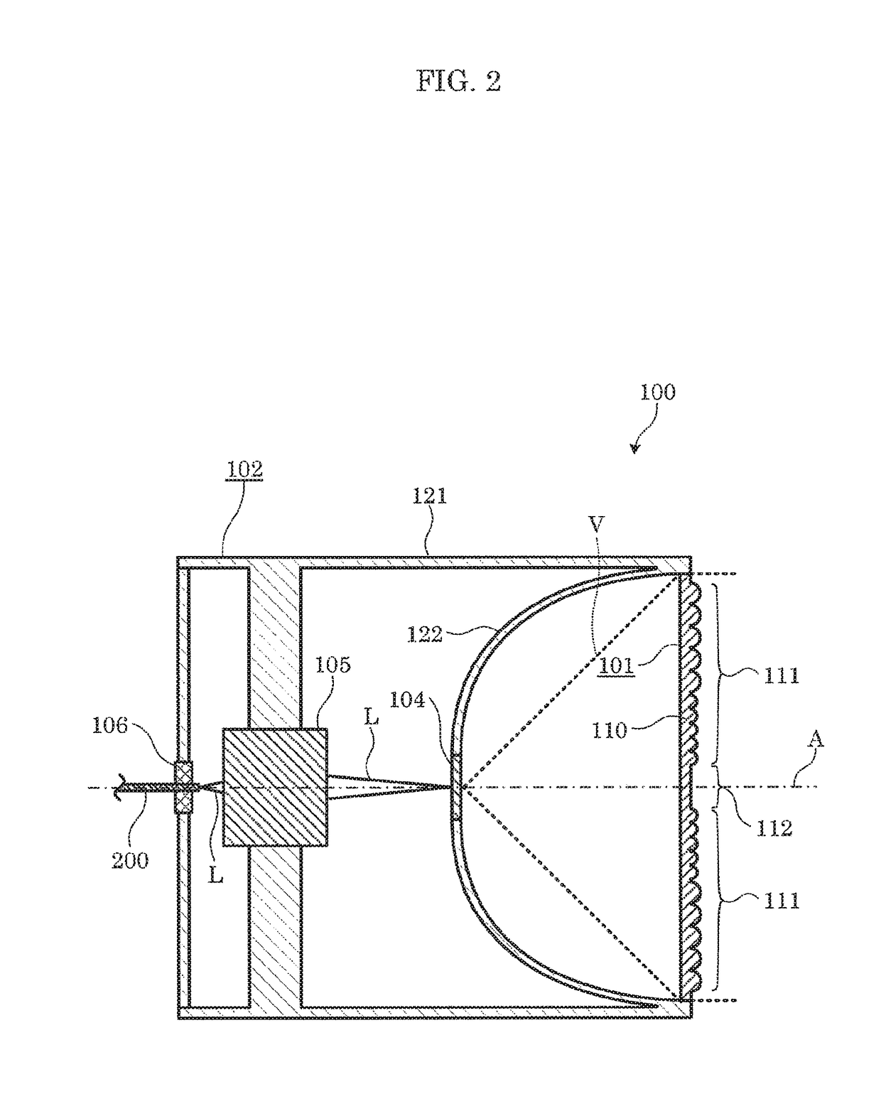
[0031]FIG. 2 is a cross-sectional view of the lighting apparatus.

[0032]As illustrated in these figures, lighting apparatus 100 is an apparatus that emits visible light, with laser light L as a light source, and includes light-emitting component 104 and lens 101. Furthermore, in this embodiment, lighting apparatus 100 includes case 102, optical system 105, and fiber attachment component 106.

[0033]As illustrated in FIG. 2, light-emitting component 104, by being irradiated with laser light L, radiates light of a different wavelength from laser light L. light-emitting component 104, for example, includes, in a dispersed state, phosphor particles which generate fluorescence when excited by laser light L, and irradiation with laser light L causes the phosphors to generate fluorescence that is of a different wavelen...


PUM


Abstract

A lighting apparatus having laser light as a light source is provided. The lighting apparatus includes: a light-emitter which radiates light of a wavelength different from a wavelength of the laser light; and a lens including a light distribution controlling structure that controls distribution of the light radiated from the light-emitter. The lens is disposed opposite a laser light entry side of the lighting apparatus. The light-emitter is disposed between the lens and the laser light entry side. The lens integrally includes, along an optical axis of the laser light, a light-dispersing structure configured to disperse the laser light.

Description

CROSS REFERENCE TO RELATED APPLICATIONS[0001]This application claims the benefit of priority of Japanese Patent Application Number 2015-206795 filed on Oct. 20, 2015 and Japanese Patent Application Number 2016-126776 filed on Jun. 27, 2016, the entire contents of which are hereby incorporated by reference.BACKGROUND[0002]1. Technical Field[0003]The present invention relates to a lighting apparatus having laser light as a light source.[0004]2. Description of the Related Art[0005]Conventionally, there are lighting apparatuses which include a light-emitting component containing phosphors that emit light with laser light transmitted by an optical fiber as excitation light, and illuminate by converting the laser light into light of a desired color. Since the laser light to be used as excitation light has a high energy density, there is a need for a technique for preventing the laser light from directly entering the eyes of a person even in the case where the light-emitting component fall...

Claims


Application Information

Patent Timeline
Patent Type & Authority Patents(United States)
IPC IPC(8): F21K9/64F21V8/00F21V5/04F21V7/00F21S8/04F21V3/04G02B5/18F21W131/405F21Y115/30
CPCF21K9/64F21S8/04F21V3/049F21V5/04G02B6/0006G02B6/0008F21V7/0091G02B5/1866F21W2131/405F21Y2115/30F21V5/045G02B5/0221G02B5/0263
Inventor NAKANO, YOSHIYUKI
Owner PANASONIC INTELLECTUAL PROPERTY MANAGEMENT CO LTD
Why Eureka
Try Eureka