Side release buckle fastener with semi rigid insertion structure

a technology of insertion structure and side release buckle, which is applied in the direction of garment fasteners, fastenings, helmets, etc., can solve the problems of limiting the ability for finer incremental adjustments, time-consuming, and cumbersome disconnection

Active Publication Date: 2018-12-25
INVERTLOCK DFM LLC
View PDF12 Cites 7 Cited by
  • Summary
  • Abstract
  • Description
  • Claims
  • Application Information

AI Technical Summary

Benefits of technology

[0011]An improved fastening device containing a lengthwise semi-rigid insertion structure with lateral opposing ridges configured to slide-ably enter a receiving enclosure shell assembly having lateral pivoting latches is hereby introduced. These latches are arranged in an inverted fashion and are given compliancy bias so as to have their detent tips move inward, ensuring locking together with insertion structure upon reversed movement. Arrangement produces a simplified ratcheting effect facilitating ease of adjustment. Release of insertion structure is achieved by press in of exposed lateral lever surfaces of thus removing locking engagement with insertion structure.

Problems solved by technology

A significant number of them require cumbersome, time consuming disconnection of the belt or strap to subsequently allow tightening or loosening adjustment.
Oftentimes, on account of mechanical strength limits and manufacturing process restrictions, minimum allowable spacing between belt holes limits ability for finer incremental adjustments.
Additionally, should a secured belt be currently under a continuous and high level of tensile load, it often can be awkward, time consuming, and a safety risk to manually disengage in order to adjust.
Should a person have limited functionality in one or both hands, or have missing fingers, adjustment of a common buckle and prong pants belt can become a difficult, tedious, time consuming procedure.
These style buckle configurations, while allowing for quicker and easier side release disconnection and connection, generally have strap attachment provisions that are sometimes difficult and cumbersome to manipulate, especially if the buckle is engaged, or if the belt is under significant tension.
The issue becomes more pronounced should the buckle be a heavier duty type using a thick belt or webbing material with limited flexibility.
As with the case of the common prong in hole buckle belt, adjustment of these Tracy type buckles when attached to heavy grade strapping typically requires disengagement and subsequent tedious manipulation of the strap thru multiple loops and or accessory slides or adjusters.
Additionally, Tracy style configurations have latches with catch surfaces subject to deforming in a manner which increases risk of sliding apart when under increased high tensile load.
Hortnagl style buckle style belts however, also suffer Tracy type buckle drawback of usually necessitating disengagement so as to facilitate manipulation and adjustment of attached strapping, and especially when using heavy grade belt strap materials.
With heavy duty thicker gage belts designed to sustain reliable operation under high tension, their functional necessity to have a secure grasp of an stub end of a thick strap subsequently disadvantages their ease of slide-able strap re-adjustment.
These type ratcheting-buckle structures in general tend to have complex assembly configurations, necessitating use of many intricate parts with delicate cooperative arrangements.
Subsequently production of such ratchet styles generally have significantly higher manufacture costs.
Additionally the intricacy of these mechanisms are at increased degradation risk from repeated exposure to environmental contaminants which often allows fine debris ingress resulting in propensity for jamming or premature wear.
Such a downward force requirement severely limits simultaneous ergonomic use of actuation hand's unengaged fingers ability to induce slide-able motion to the corresponding strap.
Use of this type structure would be highly unsuitable in belt or strap applications requiring flexibility and repeated manual manipulation which sometimes can be quick and slide-ably abrupt.

Method used


Image

  • Side release buckle fastener with semi rigid insertion structure
  • Side release buckle fastener with semi rigid insertion structure
  • Side release buckle fastener with semi rigid insertion structure

Examples


Embodiment Construction

. [1-6]

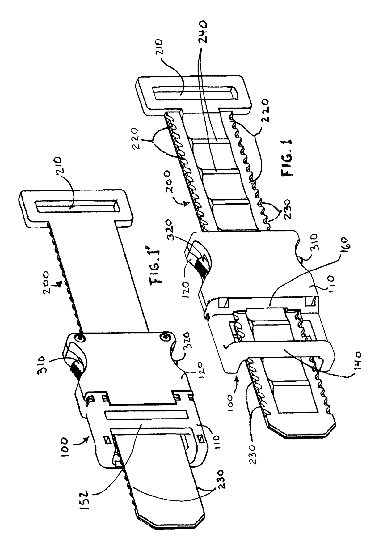
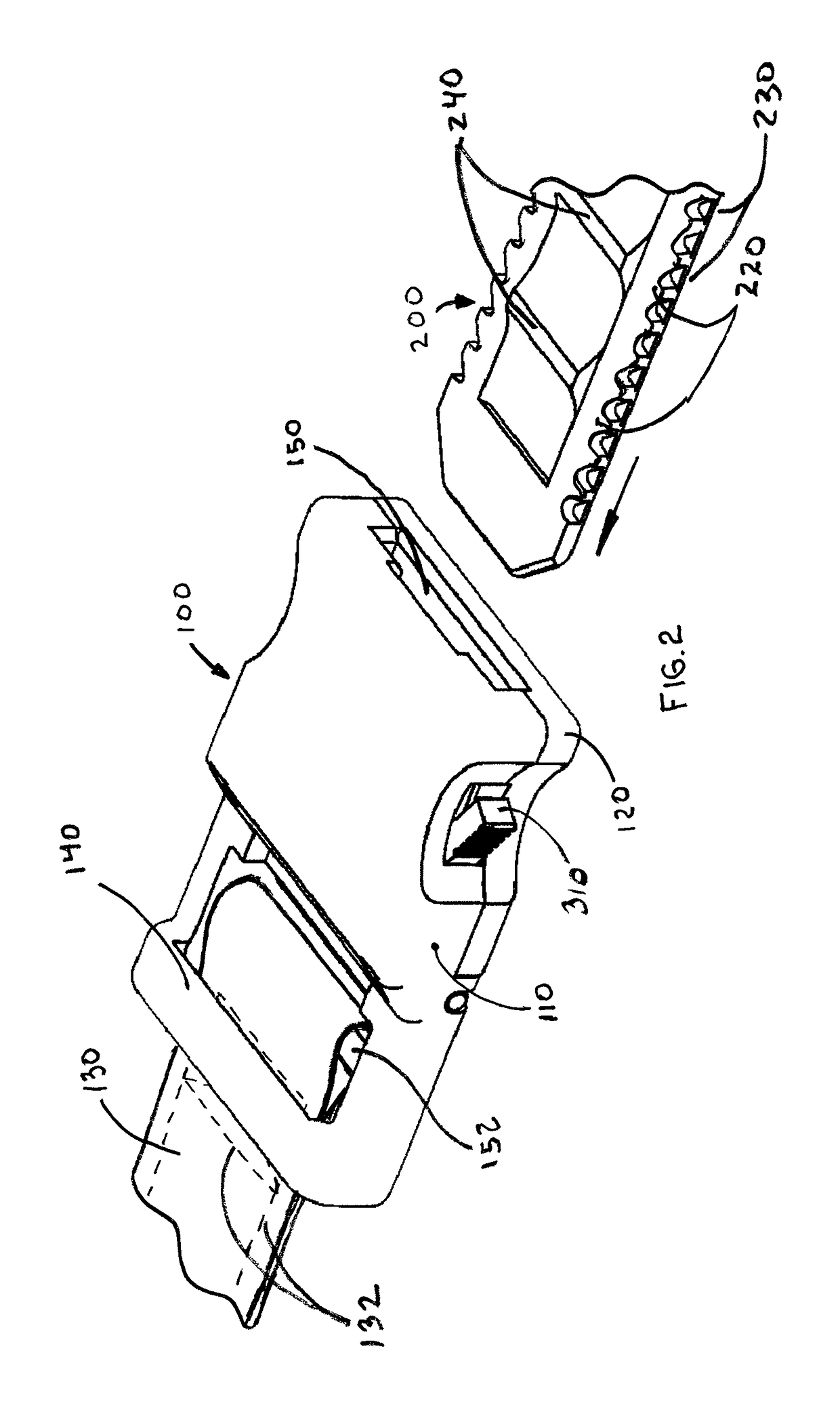
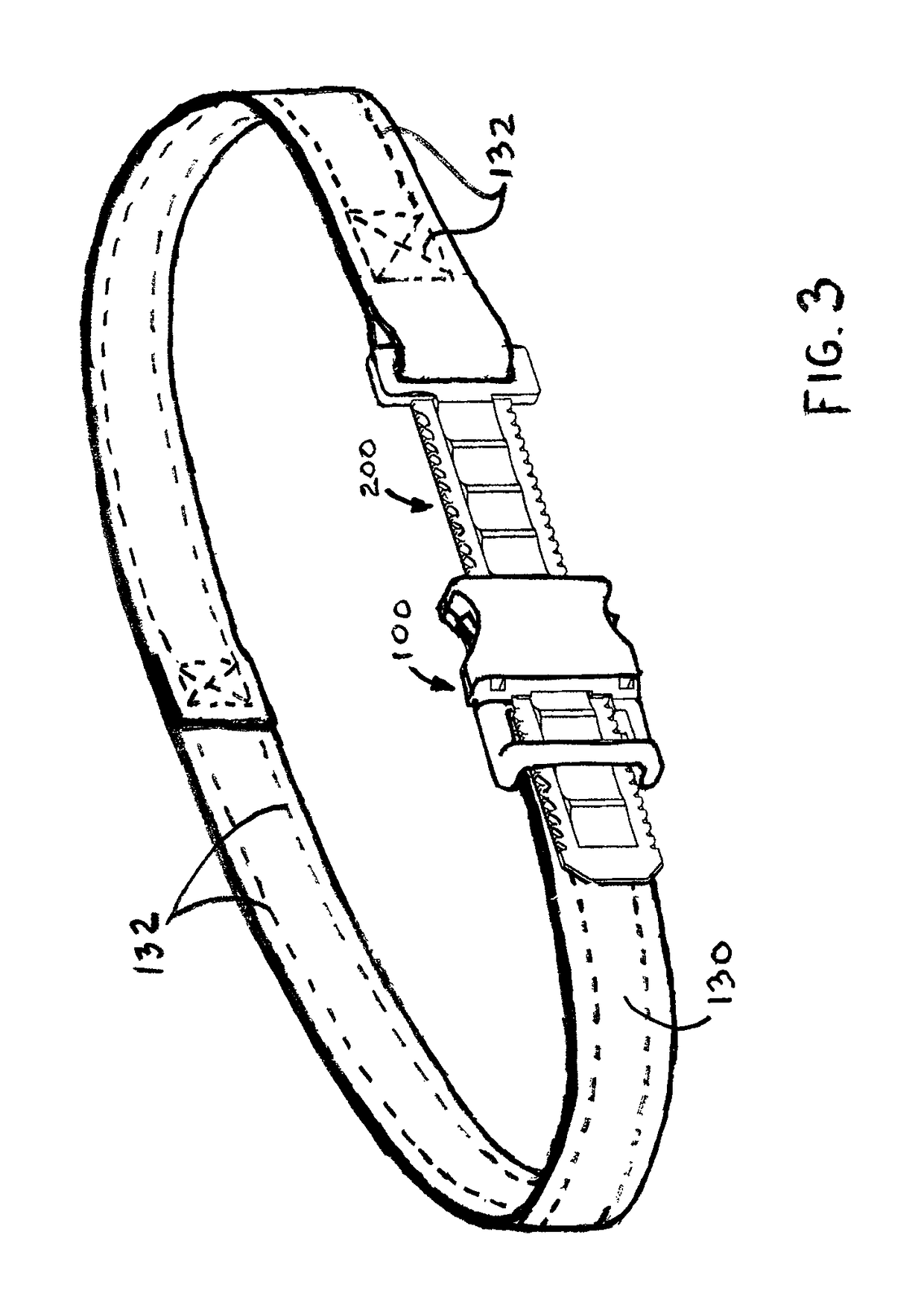
[0023]The belt embodiment has a receiving enclosure assembly part 100 and an insertion structure part 200. Insertion part has an eyelet opening 210 to connect to a belt 130 and receiving part has crossbar 152 also for connecting to the belt. Belts can be configured for permanent attachment via stitching 132 to both insertion and receiving parts. Alternatively both the receiving part and insertion part may include several belt openings for and adjustable connection to an open ended belt.

[0024]The receiving enclosure has a top cover 110 and a bottom cover 120, and laterally located inverted latches 310 and 320. The receiving part also has an insertion opening 150 and an exit opening 160. Preferably insertion part is made of plastic material such as Nylon or Delrin thus providing flexibility yet good structural integrity for small features such as bosses and ridges. The receiving part can be made of metal or plastic depending on application requirements and cost targets.

[0025]Ad...


PUM


Abstract

A quick fastening and disconnecting buckle fastener system is configured for improved ease of one handed adjustment. For reliable locking, and convenient operation the system incorporates lateral pivoting latches assembled within a receiving enclosure shell having entry and exit openings accommodating a lengthwise semi rigid insertion structure containing lateral opposing ridges. Said ridges cooperate with said latches in a manner allowing ease of continued entry directional movement and securely locking should motion be reversed. Purposeful disconnection is activated thru simultaneous press in of side levers releasing latch locking of insertion structure thereby allowing movement in a reversed direction. Use of aforementioned fastening device removes need for having to re-lace belt thru attachment loops or additional sliding hardware as means of adjustment.

Description

CROSS REFERENCE TO RELATED APPLICATIONS[0001]This application claims the benefit of provisional patent application Ser. No. 62 / 247,205 file 2015 Oct. 28 by present inventor, the entire disclosure of which is incorporated by reference.BACKGROUND—PRIOR ART[0002]The following is a tabulation of some prior art that presently appears relevant:[0003]U.S. patentsU.S. Pat. No.Kind CodeIssue DatePatentee8,561,268B22013 Mar. 22Hortnagl2,867,8121959 Jan. 13Roth5,606,7791997 Mar. 4Lu[0004]U.S. patent application PublicationsPublication NrKind CodePubl. DateApplicant2015 / 0033457A12015 Feb. 5Tryner2015 / 0113770A12015 Apr. 30LaatzBACKGROUND ART[0005]There are many buckles, belts, straps, and fastener configurations in application today to secure objects. A significant number of them require cumbersome, time consuming disconnection of the belt or strap to subsequently allow tightening or loosening adjustment. For instance, in order to adjust a common buckle pants belt having a square or oval metal f...

Claims


Application Information

Patent Timeline
Patent Type & Authority Patents(United States)
IPC IPC(8): A41F1/00A44B11/26A44B11/25A43C11/12A42B3/08A42B3/32
CPCA41F1/008A44B11/266A44B11/2592A43C11/12A42B3/08A42B3/326Y10T24/1498Y10T24/45702Y10T24/45246A42B3/205A43C11/14
Inventor ORTEGA, JOSE LUIS
Owner INVERTLOCK DFM LLC
Why Eureka
Try Eureka