Fractionator annular drain apparatus and method

a technology of annular drain and flotation tank, which is applied in the direction of water cleaning, separation process, waste water treatment from quaries, etc., can solve the problems of unsatisfactory oil, unprofitable, and certainly unprofitable at the market price, and the entire separation process and handling process is themselves problematic, so as to achieve more pressure or head height, high viscosity, and more force and energy to mov

Active Publication Date: 2018-12-25
SNORKELS IP LLC
View PDF11 Cites 3 Cited by
  • Summary
  • Abstract
  • Description
  • Claims
  • Application Information

AI Technical Summary

Benefits of technology

[0021]In fact, it is possible to use such piping to remove oil. However, it has been found in accordance with the invention that removing the very best oil from the very highest location possible provides a more efficient and cost effective extraction method for separating and drawing out oil that will be within specification. Thus, it has been found that taking oil only from the very best oil available provides the benefit of improving compliance with specifications. It also permits oil therebelow to continue to dwell in the separation tank, further separating. Longer dwell times are longer separation times for water to drift downward along with basic solids, while the oil continues to separate upward.
[0033]On the one hand, higher viscosity requires more force and energy to move, and therefore more pressure or head height to move a fluid against the drag forces of surrounding fluids or solids. On the other hand higher viscosity tends to result in greater momentum transfer between adjacent molecules of the fluid, thereby transferring momentum and increasing speed or keeping the flow together.
[0034]It has been found that creating a flow field controller, solves the vortex problem. The flow field controller doubles as a spacer plate, keeping supporting buoys away from the snorkel head. It prevents the snorkel head from gaining access to air at the top surface or along the surfaces of the buoys.
[0036]The effective depth is increased by the distance along the radius from the outer perimeter of the spacer plate to the apertures in the snorkel head suspended therebelow. This distance gives opportunity for surrounding oil to respond to the buoyancy difference between air and oil. Oil will force the air toward the surface, and replace it with heavier oil. Thus, the flow field controller controls the flow field by expanding the effective spherical distance to which flow is restricted to gain access to the apertures of the snorkel head.
[0038]That minimum flow path provides two features. One is time. Time permits oil to back flow or fill in and force out air that may be drawn into the flow field. Second, the minimum flow path provides an equalization of the distance fluid must travel to arrive at the snorkel. It effectively makes or reduces a sphere, otherwise filled with air in its top hemisphere, into a walled off lower hemisphere of liquid only.
[0042]It requires the same distance of travel, the same viscous drag, and the same acceleration from the cross sectional area at the maximum radius or diameter of the sphere to the smallest diameter sphere constituted around the inlet. It thereby imposes uniformity on the flow field of oil traveling to the inlet.

Problems solved by technology

However, eventually, some quantity of oil will result from the various separation processes that are below the specified purity.
Oil that does not meet that specification is either unsalable, and certainly unsalable at the market price, or must be disposed of at a lower price and in another manner.
However, such processing is expensive and difficult.
Moreover, the entire separation processes and handling processes are themselves problematic.
Minimizing the risk of mixing separated constituents is difficult to achieve.
Withdrawing oil without entraining a nearby layer of water is a typical challenge.
Cleaning and draining tank bottoms clinging to floors and walls present their own problems, as well.

Method used


Image

  • Fractionator annular drain apparatus and method
  • Fractionator annular drain apparatus and method
  • Fractionator annular drain apparatus and method

Examples


Embodiment Construction

[0082]It will be readily understood that the components of the present invention, as generally described and illustrated in the drawings herein, could be arranged and designed in a wide variety of different configurations. Thus, the following more detailed description of the embodiments of the system and method of the present invention, as represented in the drawings, is not intended to limit the scope of the invention, as claimed, but is merely representative of various embodiments of the invention. The illustrated embodiments of the invention will be best understood by reference to the drawings, wherein like parts are designated by like numerals throughout.

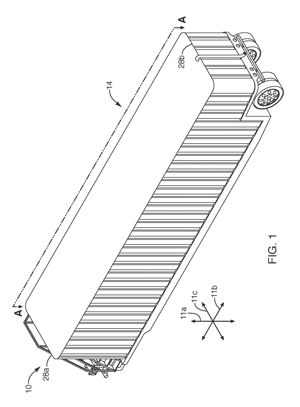
[0083]Referring to FIG. 1, in one embodiment of an apparatus and method in accordance with the invention, a system 10 may provide significant improvements to separation of comparatively higher quality oil, meaning within a specification set by a refinery as a threshold level of quality for sale to that refinery. For example, ref...


PUM

PropertyMeasurementUnit
angleaaaaaaaaaa
temperatureaaaaaaaaaa

Abstract

A tank system may be conventional and fixed, or mobile, such as a fracking fluid or other tank trailer. A drain port thereof is fitted with an adapter connecting a snorkel system to drain liquids from near the top of the liquid level in the tank. A snorkel head at the extreme distal end of a tube near the longitudinal center of the tank is suspended by a system of buoys. A flow field controller plate resists formation of vortices near the snorkel head, so it can operate as near the surface as possible, withdrawing the highest grade oil efficiently. At its exit, the proximal end of the tube drains oil through an inner conduit of an adapter at a penetration in the wall of the tank. The adapter forms an annulus around the inner conduit draining tank bottoms directly from the tank.

Description

RELATED APPLICATIONS[0001]This application claims the benefit of U.S. Provisional Patent Application Ser. No. 62 / 208,945, filed Aug. 24, 2015, and U.S. Provisional Patent Application Ser. No. 62 / 259,856, filed Nov. 25, 2015. Both of which are hereby incorporated by reference in their entirety.BACKGROUNDField of the Invention[0002]This invention relates to petroleum production and, more particularly, to novel systems and methods for separation of oil.Background Art[0003]Petroleum production will typically produce some quantity of petroleum, also referred to as crude, or crude oil. It will typically also produce a certain amount of water, typically constituted as brine containing salt and various other minerals. Also, natural gas (methane) and other trace gases will often result. Within these fluids may also arrive from a well head certain quantities of basic sediments, including precipitates, sand, rock chips, other solids, and so forth.[0004]Various separation techniques exist for s...

Claims


Application Information

Patent Timeline
Patent Type & Authority Patents(United States)
IPC IPC(8): C02F1/40B01D17/02E02B15/10B01D21/00B01D21/30B01D21/24C02F1/00C02F103/10
CPCB01D17/0214B01D21/0024B01D21/2444B01D21/307C02F2201/008C02F2001/007C02F2103/10F16L39/005C02F1/40B01D21/2433
Inventor BELL, DAVID A.MILLER, C. MICHAELTUCKER, KRISTENHIGLEY, JOHN MICHAEL
Owner SNORKELS IP LLC
Why Eureka
Try Eureka