
Torque balancing roll forming machine

a roll forming machine and torque balancing technology, applied in the direction of rolling speed control device, metal rolling arrangement, manufacturing tools, etc., can solve the problems of uneven load, rapid tooling wear, roll scuffing of materials, etc., to reduce the output speed, increase torque output, and significant flexibility in tooling

Active Publication Date: 2018-12-25
BRANER USA INC
View PDF12 Cites 0 Cited by
  • Summary
  • Abstract
  • Description
  • Claims
  • Application Information

AI Technical Summary

Benefits of technology

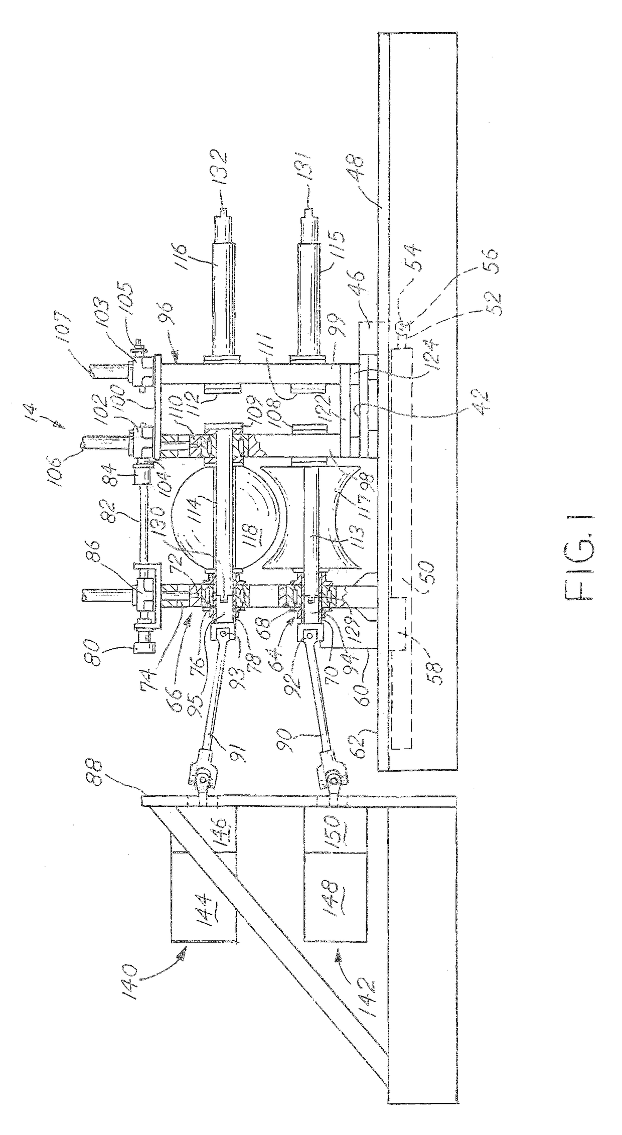
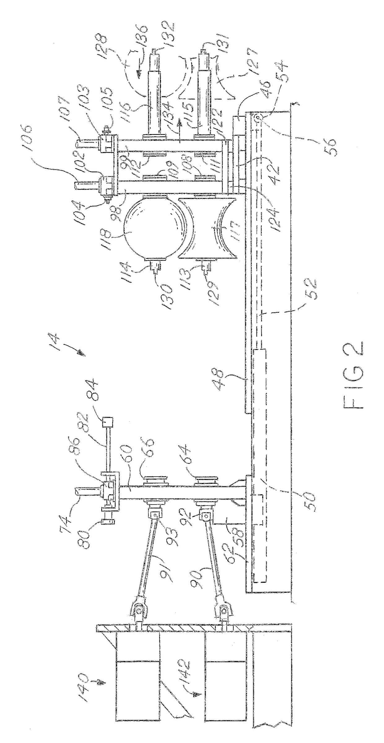
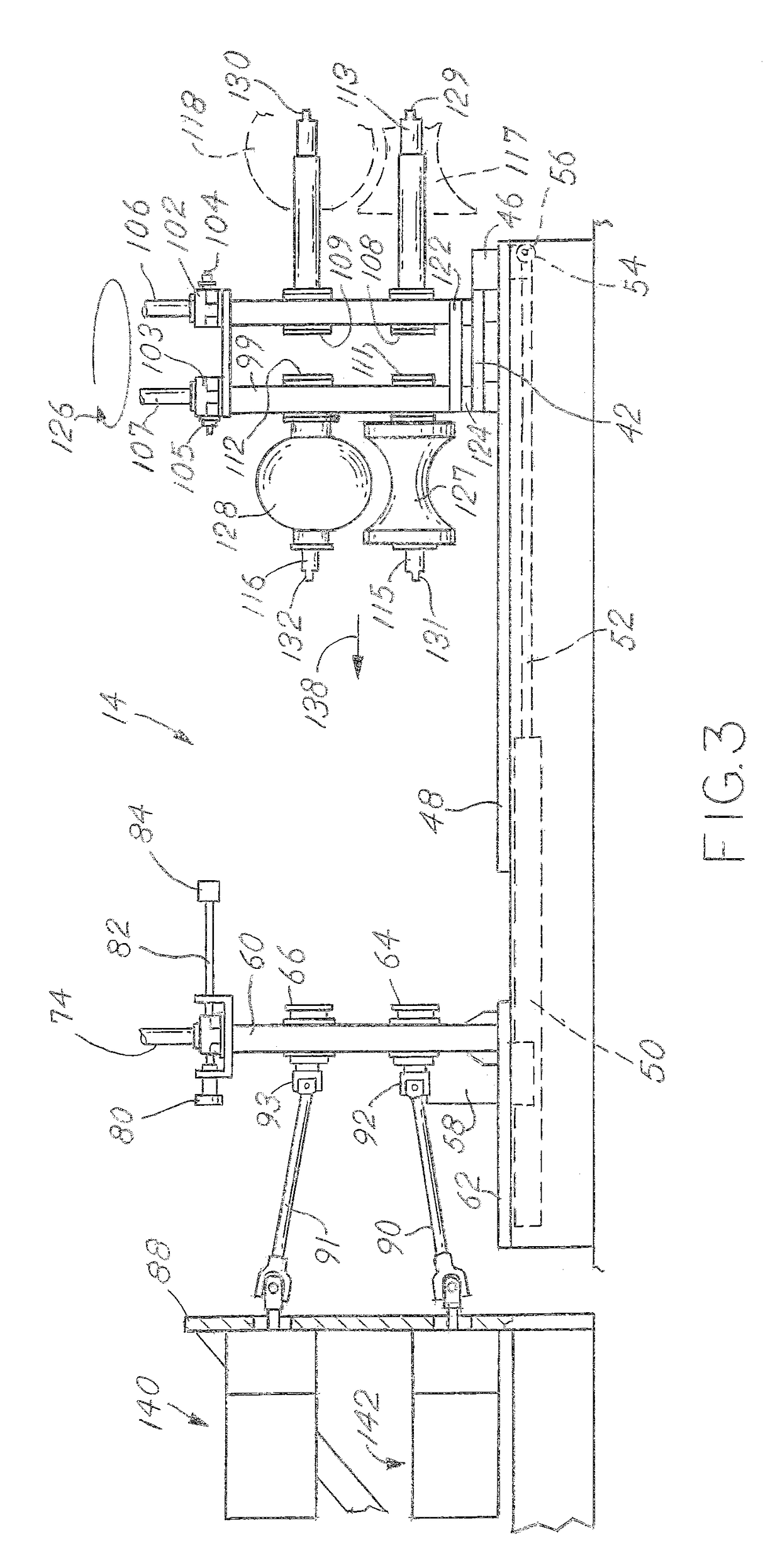
[0002]The present disclosure describes an improvement to a roll former. As is known in the art, roll formers have a series of rollers. In this invention, each roller is driven independently, allowing significant flexibility in tooling and appropriate speed settings from roller to roller and station to station. Instead of a traditional gearbox arrangement, individual motors (electric or hydraulic) drive individual rollers. As is typical of a roll former, the individual output shafts of the motors are coupled to the rollers through shafts with flexible joints on each end. Frequently, each motor has its own gearbox to reduce the output speed and increase torque output, as roll forming lines can run slower than an optimum motor rotational speed. As material is fed into the machine, the operator can tailor speed and torque unique to each roller to optimize the process and reduce wasted power. The invention provides significant benefits over the prior art.

Problems solved by technology

Further, windup (where a biased torque builds up between two rotating members) causes uneven load, rapid tooling wear, roll scuffing of the material, and possibly catastrophic failure of the gearbox.

Method used


Image

  • Torque balancing roll forming machine
  • Torque balancing roll forming machine
  • Torque balancing roll forming machine

Examples


Embodiment Construction

[0010]As is known in the art, a roll forming machine takes a flat strip of material and shapes it into a continuous cross-sectional desired shape, such as tubing. Frequently, the roll forming machine is a portion of a production line where the flat strip is provided to the machine from another machine, such as an uncoiler or slitter. After the machine makes the tubing, the tubing may be finished by other processes, such as cutting, end finishing, and stacking. This specification is primarily dedicated to the machine portion of the production line.

[0011]Referring first to the drawings of FIGS. 4 and 5, reference numeral 10 generally designates a roll forming line, commonly used in making cylindrical tubes from sheet metal products. As shown in FIG. 4, a typical line 10 includes numerous machines which form the various sections of the line. These include forming section 12, which includes mill stands 13, 14, 15, 16 and 17; a cluster section 18 which includes mill stands 19, 20 and 21;...


PUM

PropertyMeasurementUnit
rotational torqueaaaaaaaaaa
torqueaaaaaaaaaa
shapeaaaaaaaaaa

Abstract

A roll forming machine is provided having a series of mill stands, each having an upper roller and a lower roller that performs a roll forming step. The upper roller rotates on a central axis that is parallel to the lower roller. Each roller has a driven feature that connects to a driving feature. The driving feature for the upper roller can rotate independently from the driving feature of the lower roller. A control system is capable of monitoring, controlling, and displaying the individual torque and speed of separate motors that rotate the individual driving features.

Description

BACKGROUND OF THE INVENTION[0001]This present disclosure relates to roll forming machines, specifically how the individual stations are driven. Each station has an upper roller and a lower roller that pinch the material to progressively shape it. Each roller must be rotationally driven to move the material along and assist the forming. Currently, the stations are all driven from one power source, commonly an electric motor. The shaft of the electric motor is affixed to a single gearbox, where the rotation from the motor is then divided up and split up into several output shafts, each driving a roller. For example, in U.S. Pat. No. 5,450,740, one gearbox drives several rollers. Because of slightly different speeds of both upper and lower rollers, along with slightly different speeds of the rollers from station to station, a fixed gearbox that provides the exact same rotational speed to each roller, binding and torque spikes can occur. Further, windup (where a biased torque builds up ...

Claims


Application Information

Patent Timeline
Patent Type & Authority Patents(United States)
IPC IPC(8): B21B37/46B21B35/14
CPCB21B35/14B21B37/46B21C37/08
Inventor MATSUNAGA, DOUGLAS S.
Owner BRANER USA INC
Learn More