
Firearm adapter configured to mount to a firearm frame

a technology for adapters and firearms, applied in the field of firearm adapters, can solve the problems of increased cost, increased complexity, and inability to meet the requirements of firearms industry, and achieve the effects of eliminating cycling problems, convenient and fast installation, and convenient retrofitting

Active Publication Date: 2018-12-25
DEVHOLD INC
View PDF16 Cites 4 Cited by
  • Summary
  • Abstract
  • Description
  • Claims
  • Application Information

AI Technical Summary

Benefits of technology

This patent describes a device that allows gun owners to easily and safely attach a suppressor to various firearms using a single adapter and without the need for tools. The device includes a firearm adapter with a rail attachment, vertical guide, and a bore alignment structure. The device also includes a compressible grommet for a proper seal between the adapter and the barrel of the firearm. The technical effects of this invention include the elimination of cycling issues, easy installation and repeatability, and the adaptability to different firearm geometries.

Problems solved by technology

Unfortunately, rail systems often have inconsistent dimensions and will vary in size, shape, and dimension between firearms.
The firearm industry has not established a universal standard for rail system dimensions and most are aftermarket modifications lacking the consistencies that might be present if the rail systems were originally manufactured as part of the firearm frame.
This attachment method, however, comes with additional complications when the firearm employs a “floating” barrel housed within a slide (a.k.a. a “locked breech barrel”), such as the Glock firearms.
As the slide attempts to move back into a firing position, the angled projectile is unable to slide into the proximal end of the barrel and the weapon jams.
This method, however, creates another potentially catastrophic issue revolving around the alignment of the barrel and the suppressor attached to the adapter.
As already explained, rail systems have inconsistent dimensions.
Furthermore, where a definition or use of a term in a reference, which is incorporated by reference herein, is inconsistent or contrary to the definition of that term provided herein, the definition of that term provided herein applies and the definition of that term in the reference does not apply.

Method used


Image

  • Firearm adapter configured to mount to a firearm frame
  • Firearm adapter configured to mount to a firearm frame
  • Firearm adapter configured to mount to a firearm frame

Examples


Embodiment Construction

[0076]In the following detailed description of the present invention, reference is made to the accompanying drawings, which form a part thereof, and within which are shown by way of illustration specific embodiments by which the invention may be practiced. It is to be understood that other embodiments may be utilized and structural changes may be made without departing from the scope of the invention.

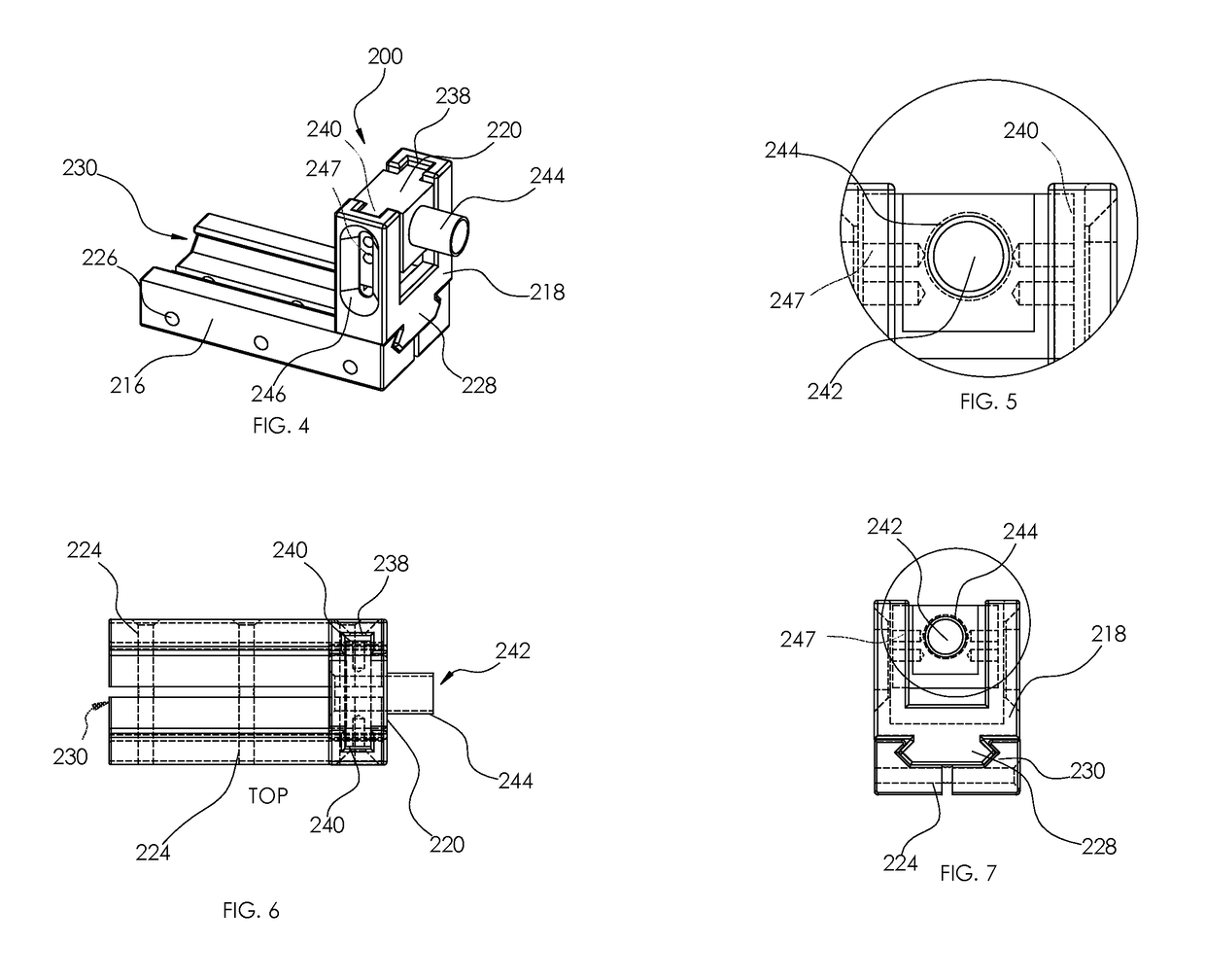
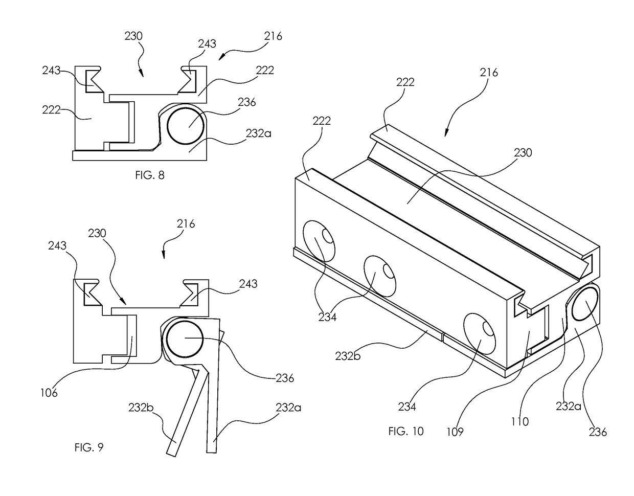
[0077]The present invention is a universal firearm adapter configured to mount to the frame of a firearm or a rail system on the frame of a firearm. The adapter of the present invention includes a frame or rail attachment (hereinafter referred to as “rail attachment”) configured to attach to a plurality of dimensionally inconsistent frames / rails and a bore alignment assembly configured to axially align the adapter bore with the barrel bore regardless of the dimensional and axial inconsistencies of the barrel and its bore.

[0078]Referring to FIGS. 4-10, an embodiment of the firearm adapte...


PUM


Abstract

A universal firearm adapter configured to mount to the frame of a firearm. The adapter easily, quickly, accurately, securely, concentrically and repeatably, with or without tools, attaches a suppressor or suppressor adapter to the frame or rail system of a firearm. The adapter includes a rail attachment configured to attach to a plurality of dimensionally inconsistent frames / rails and a bore alignment assembly. Moreover, the adapter is configured to axially align the adapter bore with the barrel bore regardless of the dimensional and axial inconsistencies of the barrel and its bore. The bore alignment assembly preferably includes a suppressor mount axially aligned with the adapter bore thereby ensuring that the suppressor is axially aligned with the bore of the barrel.

Description

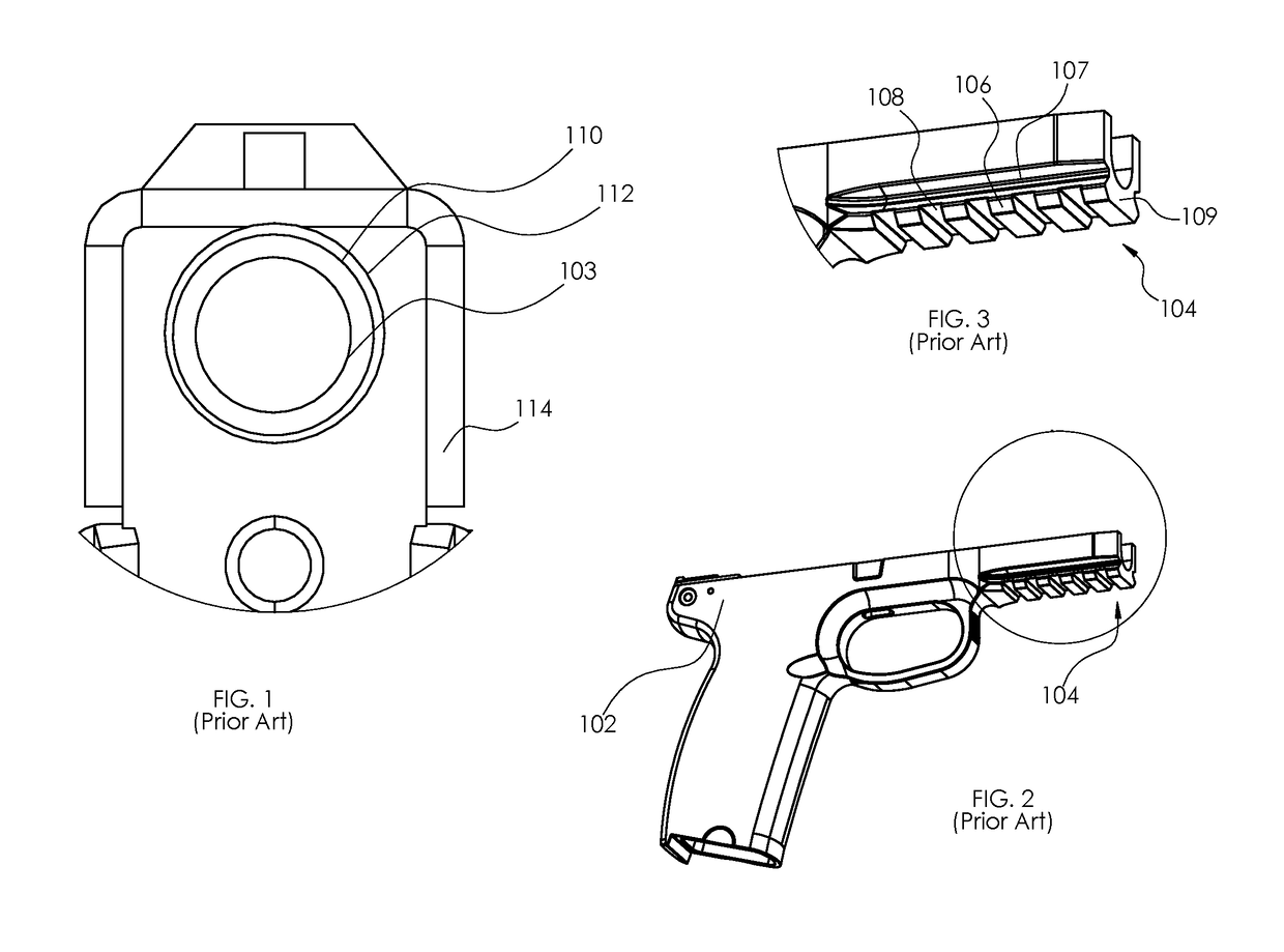
BACKGROUND OF THE INVENTION1. Field of the Invention[0001]This invention relates, generally, to firearm adapters. More specifically, it relates to a firearm adapter configured to mount to the frame of a firearm and axially align with the firearm barrel.2. Brief Description of the Prior Art[0002]Firearm accessories have grown in popularity with the evolution of firearms. Over the years these accessories have been attached to firearms through various means, most of which require permanently altering the firearm. For example, attachment of suppressors (a.k.a. silencers) typically require a gunsmith to add external threads to the muzzle end of the firearm barrel to provide a mount on which the suppressor may threadedly engage. Another example, which has become increasingly popular is the attachment of rail system 104 to the surface of a firearm 102, as depicted in FIGS. 2-3. Typically, rail systems 104 comprise equidistantly-spaced laterally-extending strips of metal 106 secured to the ...

Claims


Application Information

Patent Timeline
IPC IPC(8): F41A21/32
CPCF41A21/325F41G11/003
Inventor LEE, DARRYL S.
Owner DEVHOLD INC
Learn More