Supercharge Your Innovation With Domain-Expert AI Agents!

Optimizing water quality sensor placement for water distribution systems

a technology of water distribution system and water quality sensor, which is applied in the direction of service pipe system, mechanical equipment, instruments, etc., can solve the problems of unsuitable human consumption, unsatisfactory water quality, and loss of effectiveness of chemical additives, so as to maximize the length of pipes, optimize the placement of water quality sensors, and improve the efficiency of water quality sensors

Active Publication Date: 2018-12-25
BENTLEY SYST INC
View PDF21 Cites 18 Cited by
  • Summary
  • Abstract
  • Description
  • Claims
  • Application Information

AI Technical Summary

Benefits of technology

The patent text describes an analysis application that is used to optimize the placement of water quality sensors in a water distribution system. The two-part solution procedure involves building an impact database by simulating target scenarios and analyzing them to determine if water quality variation is detectable at each possible sensor location. The resulting database is used to calculate water quality sensor network efficiency for a set of possible sensor locations and an optimized sensor location set can be generated based on this efficiency. The optimized sensor location set is displayed to a user, who can then arrange for workers to apply water quality sensors at the indicated locations. The technical effect of this patent is to provide a systematic approach for optimizing water quality sensor placement in a distribution system.

Problems solved by technology

These factors may include the quality of the raw (un-treated) water, the processes and chemical additives the water is treated with, and the interaction of the treated water with various water distribution system components which alters its quality (e.g., cause the chemical additives to lose their effectiveness).
However, interaction with water distribution system components may impact the quality of the water, such that it is rendered unsuitable for human consumption by the time it actually reaches the end user.
Due to budgetary constraints, generally only a limited number of water quality sensors can be deployed.
However, traditionally there has not been an effective technique for determining such near optimal locations, in the context of monitoring day-to-day operation.
The resulting locations are often far from optimal.
However, the issues faced in the context of water security are generally very different than those faced when trying to monitor water quality provided during day-to-day operation of a water distribution system.
Accordingly, the prior techniques are often of limited use in the latter context.

Method used


Image

  • Optimizing water quality sensor placement for water distribution systems
  • Optimizing water quality sensor placement for water distribution systems
  • Optimizing water quality sensor placement for water distribution systems

Examples


Embodiment Construction

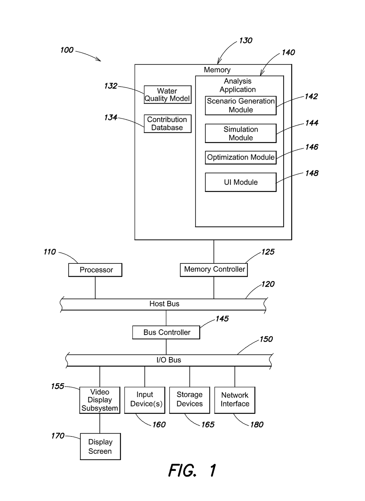
[0021]FIG. 1 is a block diagram of an example electronic device 100 (e.g., a computer) that may be used with the present techniques. The electronic device 100 includes at least one processor 110 coupled to a host bus 120. The processor 110 may be any of a variety of commercially available processors, such as an Intel x86 processor, or another type of processor. A volatile memory 130, such as a Random Access Memory (RAM) is also coupled to the host bus 120 via a memory controller 125. When in operation, the memory 120 stores processor-executable instructions and data that are provided to the processor 110. An input / output (I / O) bus 150 is accessible to the host bust 120 via a bus controller 145. A variety of additional components are coupled to the I / O bus 150. For example, a video display subsystem 155 is coupled to the I / O bus 150. The video display subsystem may include a display screen 170 and hardware to drive the display screen. At least one input device 160, such as a keyboard...


PUM

PropertyMeasurementUnit
lengthaaaaaaaaaa
concentrationaaaaaaaaaa
diameteraaaaaaaaaa

Abstract

In one example embodiment, an analysis application is used to optimize water quality sensor placement in a water distribution network by implementing a two-part optimization solution procedure, involving building an impact database, and determining an optimized water quality sensor location set using the impact database. The optimized sensor location set may indicate locations that maximize a length of pipes where water quality variations are detectable by at least one water quality sensor. Pipe wall reaction coefficients may be used as calibration parameters, with water quality indicated to be detectable at a possible sensor location when a change in its pipe wall reaction coefficients leads to a change in water quality at the possible sensor location that is greater than a threshold.

Description

RELATED APPLICATIONS[0001]The present application is a continuation-in-part of U.S. patent Ser. No. 14 / 563,668 filed on Dec. 8, 2014 by Zheng Yi Wu et al., for a “Optimizing Sensor Placement for Structural Health Monitoring”, the contents of which are incorporated by reference herein in their entirety.BACKGROUNDTechnical Field[0002]The present application relates generally to sensor placement for fluid distribution systems, and more specifically to techniques for optimizing water quality sensor placement for a water distribution system.Background Information[0003]The quality of drinking water supplied to consumers from a water treatment plant is dependent upon many factors. These factors may include the quality of the raw (un-treated) water, the processes and chemical additives the water is treated with, and the interaction of the treated water with various water distribution system components which alters its quality (e.g., cause the chemical additives to lose their effectiveness)....

Claims


Application Information

Patent Timeline
Patent Type & Authority Patents(United States)
IPC IPC(8): G01B21/16G06Q50/06G06Q10/04G01N33/18G06F17/50F17D5/02
CPCG01B21/16G01N33/18G06Q10/04G06F17/5009F17D5/02G06Q50/06E03B7/02G06F30/18G06F2113/14Y02A20/152G06F30/20
Inventor WU, ZHENG YIROSHANI, EHSAN
Owner BENTLEY SYST INC
Features
  • R&D
  • Intellectual Property
  • Life Sciences
  • Materials
  • Tech Scout
  • Unparalleled Data Quality
  • Higher Quality Content
  • 60% Fewer Hallucinations
Learn More