Control system of power transmission system of vehicle

a technology of power transmission system and control system, which is applied in the direction of propulsion parts, transportation and packaging, and propulsion using engine-driven generators, etc. it can solve the problems of reducing regenerative, deteriorating shift shock, and difficult control of regenerative torque, so as to reduce shock. the effect of deterioration

Active Publication Date: 2019-01-01
TOYOTA JIDOSHA KK
View PDF17 Cites 4 Cited by
  • Summary
  • Abstract
  • Description
  • Claims
  • Application Information

AI Technical Summary

Benefits of technology

[0007]The present disclosure is to provide a control system of a power transmission system of a vehicle, which is able to curb deterioration of shift shock, when a downshift of a mechanical speed change mechanism during coasting and increase of regenerative torque caused by braking operation take place at the same time.
[0013]In the control system of the power transmission system of the vehicle as described above, the regenerative torque produced according to braking operation is the requested regenerative torque that is increased as the braking operation amount is larger, and the rate of change of the regenerative torque is the rate of change of the requested regenerative torque. Therefore, while the requested regenerative torque is increasing such that the rate of change of the requested regenerative torque is not within the predetermined range, no downshift of the mechanical speed change mechanism is carried out. Accordingly, since there is no need to execute control for reducing shift shock while the requested regenerative torque is increasing, the actual regenerative torque that meets or follows the requested regenerative torque can be easily obtained. As a result, regenerative energy is less likely or unlikely to be reduced.
[0017]In the control system of the power transmission system of the vehicle as described above, the predetermined range is determined in advance for each gear position of the automatic transmission. Therefore, when the degree of occurrence of shift shock differs depending on the gear position of the automatic transmission, a downshift of the automatic transmission is carried out in accordance with the degree of occurrence. Namely, if a downshift is not carried out even though shift shock is unlikely to occur, completion of the downshift may be delayed. If a downshift is executed even though shift shock is likely to occur, the shock may deteriorate. With the control system as described above, the delay in completion of the downshift, or deterioration of the shock, is less likely or unlikely to occur.

Problems solved by technology

In this case, the regenerative torque is increased, and it becomes difficult to reduce regenerative torque of the motor for running the vehicle during the inertia phase of downshift of the mechanical speed change mechanism, which may result in deterioration of shift shock.
If control for reducing shift shock is performed during downshifting of the mechanical speed change mechanism, regenerative torque, which should be increased based on braking operation of the driver, is reduced, and it becomes difficult to control the regenerative torque.
As a result, shift shock may not be appropriately reduced.
Namely, if a downshift is not carried out even though shift shock is unlikely to occur, completion of the downshift may be delayed.
If a downshift is executed even though shift shock is likely to occur, the shock may deteriorate.

Method used


Image

  • Control system of power transmission system of vehicle
  • Control system of power transmission system of vehicle
  • Control system of power transmission system of vehicle

Examples


Embodiment Construction

[0029]One embodiment of the present disclosure will be described in detail with reference to the drawings.

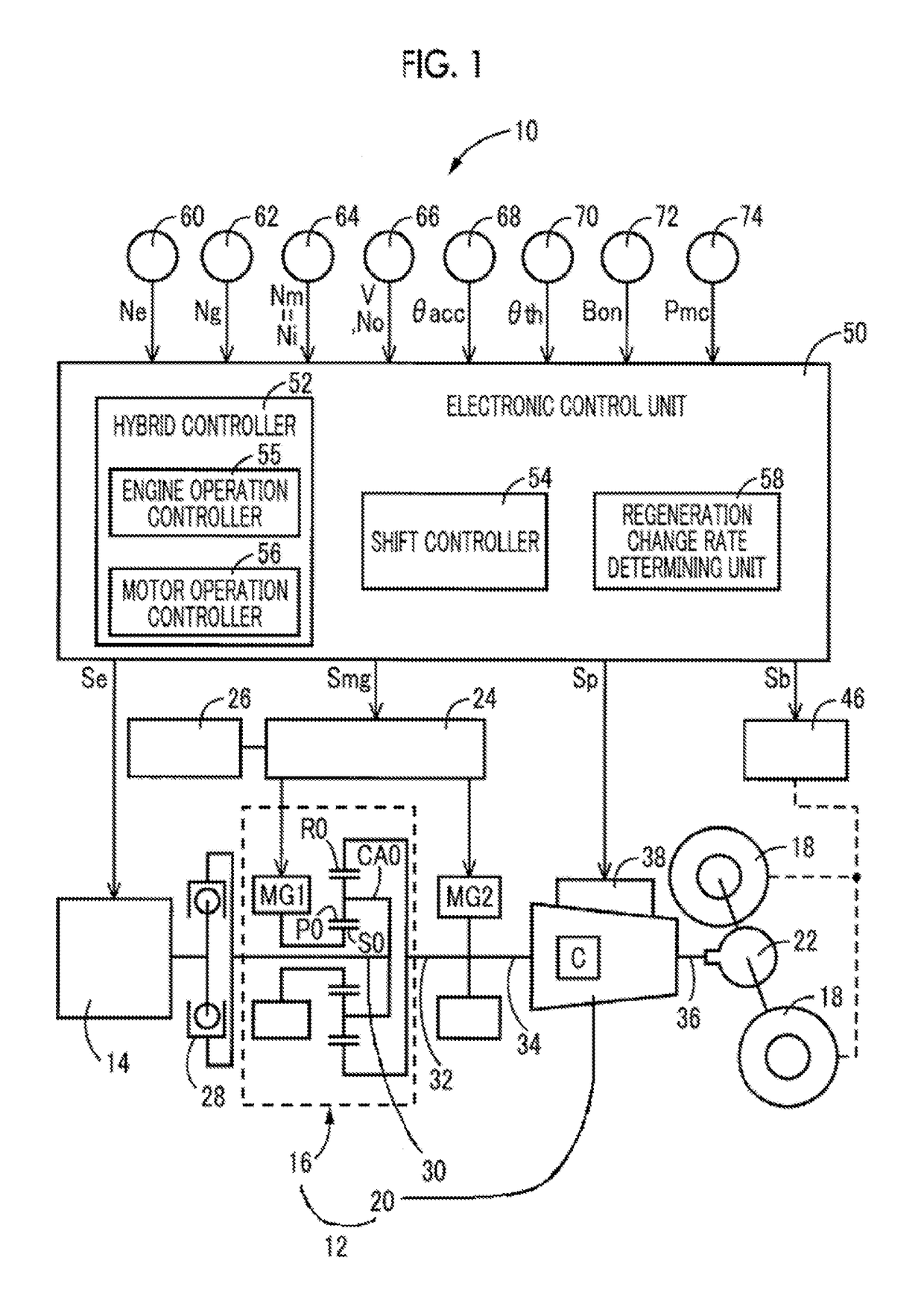
[0030]FIG. 1 schematically shows the configuration of a power transmission system 12 provided in a vehicle 10 to which this present disclosure is applied, and is also useful for explaining a principal part of a control system for various controls performed in the vehicle 10. In FIG. 1, the vehicle 10 is a hybrid vehicle including an engine 14, a first motor MG1, and a second motor MG2. The power transmission system 12 includes a power distribution mechanism 16, and an automatic transmission (AT) 20 disposed between the power distribution mechanism 16 and drive wheels 18. The power distribution mechanism 16 has a plurality of rotating elements (rotating members) to which the engine 14, first motor MG1, and the second motor MG2 are respectively coupled such that power can be transmitted between the engine 14, first motor MG1 and second motor MG2, and the corresponding rotating ele...


PUM


Abstract

A control system of a power transmission system of a vehicle is provided. The power transmission system includes an electric motor for running the vehicle, and a mechanical speed change mechanism. The control system includes an electronic control unit. The electronic control unit is configured to: perform regeneration control of the electric motor for running the vehicle during coasting of the vehicle, such that regenerative torque of the electric motor for running the vehicle provides regenerative torque produced according to braking operation; perform shift control of the mechanical speed change mechanism according to a predetermined relationship; determine whether a rate of change of the regenerative torque is within a predetermined range; and when a downshift of the mechanical speed change mechanism is determined during coasting, execute the downshift under a condition that the rate of change of the regenerative torque is within the predetermined range.

Description

INCORPORATION BY REFERENCE[0001]The disclosure of Japanese Patent Application No. 2015-243656 filed on Dec. 14, 2015 including the specification, drawings and abstract is incorporated herein by reference in its entirety.BACKGROUND[0002]1. Technical Field[0003]The present disclosure relates to a control system of a power transmission system of a vehicle including an electric motor for running the vehicle, which motor is coupled to an input rotating member of a mechanical speed change mechanism such that power can be transmitted between the electric motor and the speed change mechanism.[0004]2. Description of Related Art[0005]A control system of a power transmission system of a vehicle including an electric motor for running the vehicle, and a mechanical speed change mechanism that provides a part of a power transmission path between the electric motor and drive wheels, is well known in the art. For example, a control system of a vehicular drive unit described in Japanese Patent Appli...

Claims


Application Information

Patent Timeline
Patent Type & Authority Patents(United States)
IPC IPC(8): B60W20/30B60W30/18B60K6/445B60W30/19B60W10/192B60W10/12B60W10/18B60W20/14B60K6/547B60W10/06B60K6/365B60W10/10B60W10/08B60W10/115B60L50/16
CPCB60W20/30B60K6/445B60K6/547B60W10/06B60W10/08B60W10/10B60W10/115B60W10/12B60W10/192B60W20/14B60W30/18127B60W30/19B60K6/365Y10S903/917B60W2510/084B60W2540/10B60W2710/1005Y02T10/6239Y02T10/7258B60W20/00B60W30/18072B60W2710/083Y02T10/62Y02T10/72
Inventor KUMAZAKI, KENTASHIIBA, KAZUYUKIMATSUBARA, TOORUKOBAYASHI, NOBUFUSAYOSHIKAWA, MASATOBABA, MASAYUKISATO, SHUN
Owner TOYOTA JIDOSHA KK
Why Eureka
Try Eureka