Display device

a display device and display technology, applied in the field of display devices, can solve the problems of increased sealing process costs, increased heat generation of display devices, and increased maintenance costs of display devices, so as to prevent air flow

Active Publication Date: 2019-01-15
LG ELECTRONICS INC
View PDF18 Cites 25 Cited by
  • Summary
  • Abstract
  • Description
  • Claims
  • Application Information

AI Technical Summary

Benefits of technology

[0029]The display device according to at least one embodiment mentioned above has following effects.
[0031]Furthermore, the heat exchanger may be provided in the rear case, not the middle frame in the display device. Accordingly, the sealing structure may become simple effectively.
[0032]Still further, the rear case of the display device may be open and closed by the front case. Accordingly, the usability of the display device may be enhanced effectively.
[0034]Still further, air flow may be prevented from being performed in an unintended region of the display device.
[0035]Still further, the location of the pixel sensor may be adjusted easily and the pixel sensor may be coupled to the adjusted proper location.

Problems solved by technology

The display devices are likely to be neglected under high outdoor temperatures.
Accordingly, heat generation of the display device becomes a big issue.
The indirect cooling system has an advantage of easy ongoing maintenance that internal air is not mixed with external air and a disadvantage of additional expenses for a sealing process.
Such a disadvantage is likely to give a supplier, who assembles and manufactures the entire display devices after provided with display modules, a trouble in re-processing the provided display modules and a difficult sealing structure because of its structural complexity.

Method used


Image

  • Display device
  • Display device
  • Display device

Examples


Embodiment Construction

[0053]Description will now be given in detail according to exemplary embodiments disclosed herein, with reference to the accompanying drawings. For the sake of brief description with reference to the drawings, the same or equivalent components may be provided with the same reference numbers, and description thereof will not be repeated. In general, a suffix such as “module” and “unit” may be used to refer to elements or components. Use of such a suffix herein is merely intended to facilitate description of the specification, and the suffix itself is not intended to give any special meaning or function. In the present disclosure, that which is well-known to one of ordinary skill in the relevant art has generally been omitted for the sake of brevity. The accompanying drawings are used to help easily understand various technical features and it should be understood that the embodiments presented herein are not limited by the accompanying drawings. As such, the present disclosure should...


PUM

PropertyMeasurementUnit
pressurized forceaaaaaaaaaa
thicknessaaaaaaaaaa
heat radiationaaaaaaaaaa

Abstract

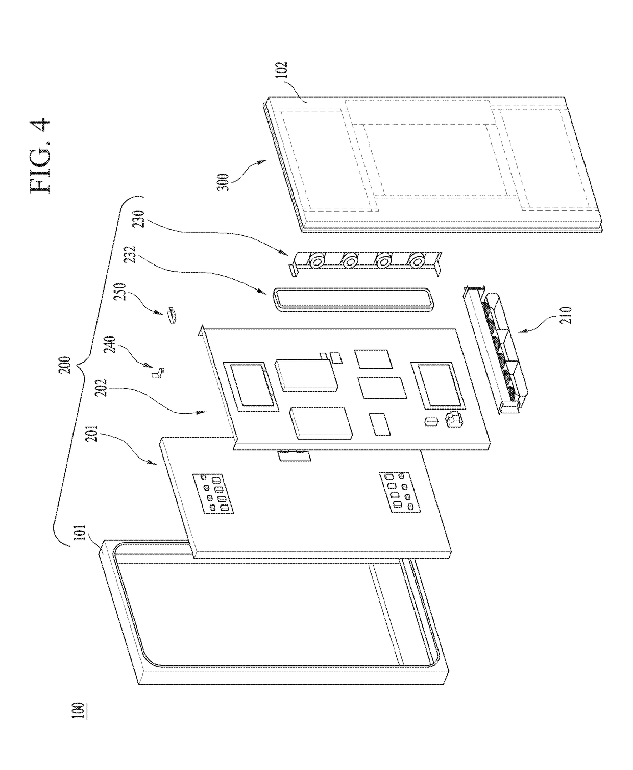
There is disclosed a display device comprising a front case, a display panel spaced apart from the front case to define a first space therebetween, a backlight unit coupled to a rear surface of the display panel, a middle frame spaced apart from a rear surface of the backlight unit to define a second space therebetween, a rear case spaced apart from a rear surface of the middle frame to define a third space therebetween, wherein the rear case is coupled to the front case to enclose the first space, the second space, and the third space such that air is not permitted to flow between the first, second, and third spaces and an exterior of the display device, a closed cooling unit disposed such that air is permitted to flow between the closed cooling unit and the first, second, and third spaces, a closed heat exchange unit disposed at the rear case and configured such that air is permitted to flow between the closed heat exchange unit and the first, second, and third spaces via the closed cooling unit, an open heat exchange unit disposed at the rear case and configured such that air is permitted to flow between the open heat exchange unit and the exterior of the display device, wherein the open heat exchange unit is further configured to exchange heat with the closed heat exchange unit and an open cooling unit configured to exhaust air from the open heat exchange unit to the exterior of the display device.

Description

CROSS-REFERENCE TO RELATED APPLICATIONS[0001]Pursuant to 35 U.S.C. § 119(a), this application claims the benefit of earlier filing date and right of priority to Korean Patent Application No. 10-2016-0124649, filed on Sep. 28, 2016, the contents of which are hereby incorporated by reference herein in its entirety.BACKGROUND OF THE DISCLOSUREField of the Disclosure[0002]Embodiments of the present disclosure relate to a display device which considers assembly and production efficiency and usability.Background of the Disclosure[0003]A display device is a general name for devices configured to output images. An image output method may be categorized into a method which facilitates direct light emitting of a panel element by using an organic light-emitting diode and another method which uses a liquid crystal panel and a backlight unit for irradiating light to the liquid crystal panel.[0004]The latter method is applied so as to describe embodiments of the present disclosure. Unique technic...

Claims


Application Information

Patent Timeline
Patent Type & Authority Patents(United States)
IPC IPC(8): G02F1/1333H05K7/20
CPCG02F1/133385G02F1/133308H05K7/20145H05K7/202G02F2001/133317G02F1/133382G02F1/133314G02F1/133317G02F1/13332H05K7/20972G02F1/133628H04N9/3144
Inventor LEE, DONGILCHOI, SANGHOPARK, JUNGKYUCHANG, MYUNGWHUNHAN, SUNGWOOK
Owner LG ELECTRONICS INC
Why Eureka
Try Eureka