Filter devices having reduced spurious emissions from lamb waves

a filter device and spurious emission technology, applied in the direction of impedence networks, electrical devices, etc., can solve the problems of inconsistent requirements and spuriousness in the frequency characteristics of saw elements, and achieve the effect of improving the quality of the communication device in which the filter device is used

Active Publication Date: 2019-01-22
SKYWORKS PANASONIC FILTER SOLUTIONS JAPAN
View PDF10 Cites 38 Cited by
  • Summary
  • Abstract
  • Description
  • Claims
  • Application Information

AI Technical Summary

Benefits of technology

[0008]Aspects and embodiments provide a filter device configured to solve one or more of the aforementioned problems. In particular, certain embodiments are directed to a filter device including at least two SAW filters and configured to reduce spurious emissions generated in a passband of one SAW filter due to a Lamb wave that propagates in the silicon dioxide film of a SAW element forming another SAW filter of the device.
[0022]According to certain embodiments, a filter device may be provided to reduce the spurious emission generated in a band of a frequency 1.2 to 1.4 times greater than the center frequency of the passband for a first filter in the device due to a Lamb wave that occurs depending on the silicon dioxide film of the SAW element forming the first filter. Therefore, quality of a communications device in which the filter device is used may be improved.

Problems solved by technology

These Lamb waves can cause spuriousness in the frequency characteristics of the SAW element.
However, this requirement can be inconsistent with other design considerations for various SAW elements.

Method used


Image

  • Filter devices having reduced spurious emissions from lamb waves
  • Filter devices having reduced spurious emissions from lamb waves
  • Filter devices having reduced spurious emissions from lamb waves

Examples


Embodiment Construction

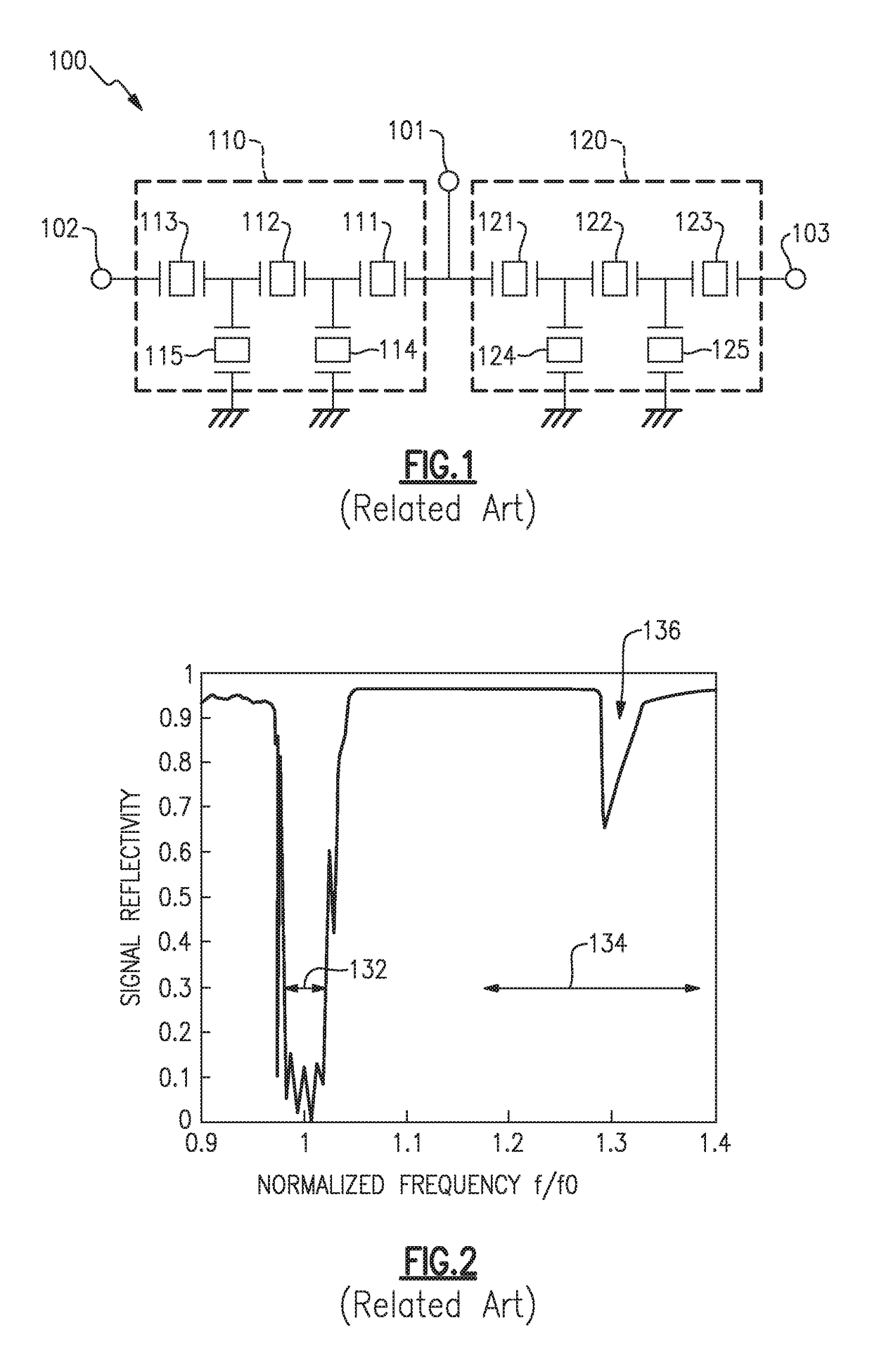
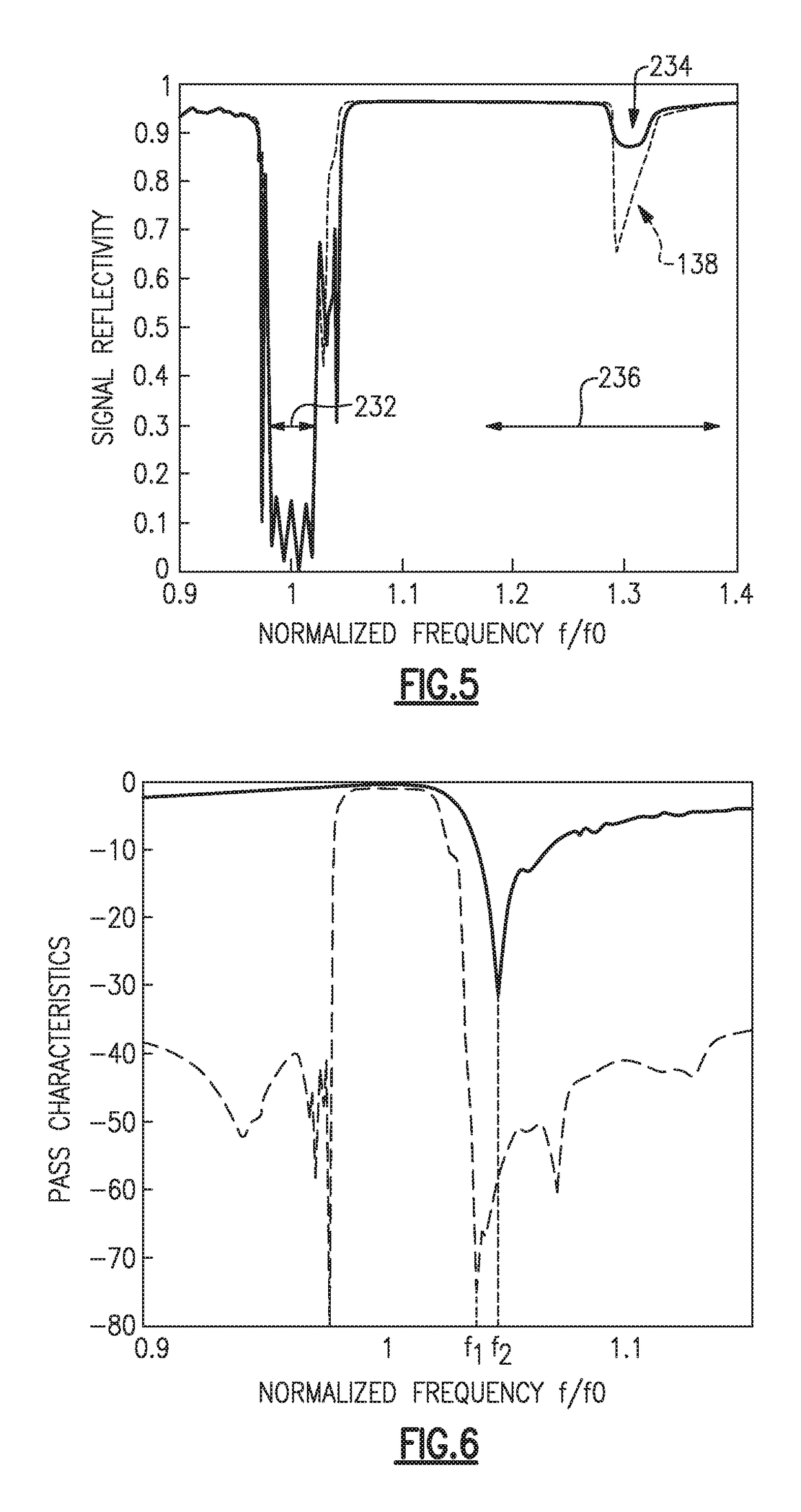
[0037]Aspects and embodiments provide filter device that reduces a spurious emission of a first filter generated in a band of a frequency 1.2 to 1.4 times greater than a center frequency of a passband of the first filter.

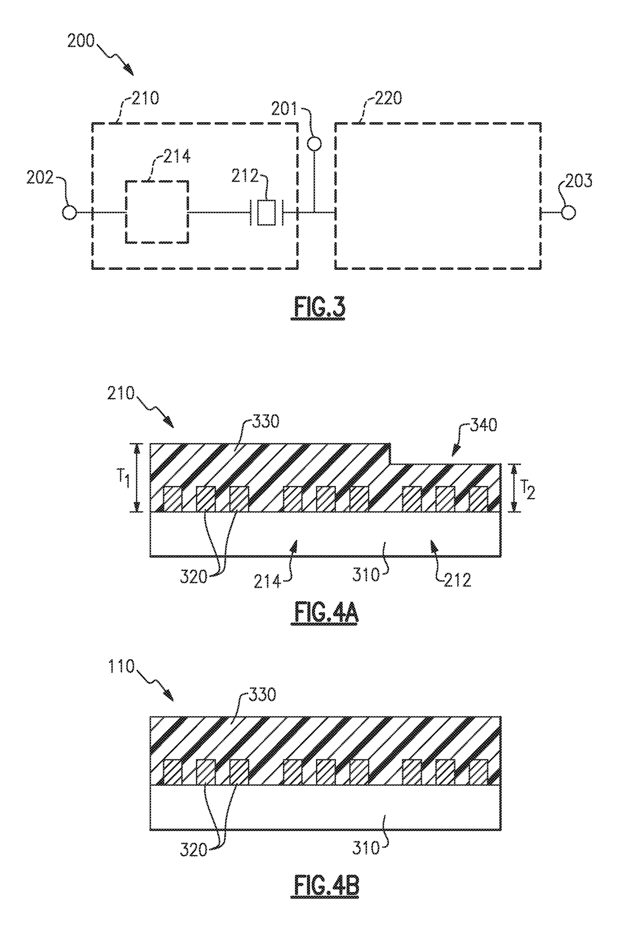
[0038]FIG. 3 is a block diagram schematically illustrating an exemplary configuration of a filter device according to certain embodiments. The filter device 200 includes a first filter 210 and a second filter 220. The first filter 210 is connected between a common contact 201, which can be connected to an antenna, and a first signal contact 202 to allow an input signal to pass through. The second filter 220 is connected between the common contact 201 and the second signal contact 203. The filter device 200 may be an antenna diplexer or antenna duplexer, for example.

[0039]The first filter 210 includes a plurality of surface acoustic wave (SAW) resonators. Only one SAW resonator 212 of the plurality of resonators (referred to as a front-end resonator hereinafter) is c...


PUM


Abstract

A filter device that reduces spurious emissions generated in a frequency band 1.2 to 1.4 times greater than a center frequency of a passband of a filter. In one example the filter device includes a first filter connected between a common contact and a first signal contact and having a first passband, and a second filter connected between the common contact and a second signal contact and having a second passband with a center frequency in a range of 1.2 to 1.4 times greater than a center frequency of the first passband. The first filter includes a SAW filter formed on a piezoelectric substrate, a SAW resonator formed on the piezoelectric substrate and connected in series between the common contact and the SAW filter, and a dielectric film covering the SAW filter and SAW resonator, the dielectric film having a reduced thickness in a region corresponding to the SAW resonator.

Description

CROSS-REFERENCE TO RELATED APPLICATIONS[0001]This application claims the benefit under 35 U.S.C. § 119(e) of U.S. Provisional Application Nos. 62 / 346,838, titled “FILTER DEVICES,” filed on Jun. 7, 2016, and 62 / 503,557, titled “FILTER DEVICES HAVING REDUCED SPURIOUS EMISSIONS FROM LAMB WAVES,” filed on May 9, 2017, each of which is herein incorporated by reference in its entirety for all purposes.BACKGROUND[0002]Conventionally, in a communication device such as a mobile phone and the like, a filter device has been used to separate signals having different bands, such as transmission and reception signals, for example. In such a filter device, one or more surface acoustic wave (SAW) elements are often used. These SAW elements can include one or more resonators, each formed by an interdigital transducer (IDT) electrode disposed on a piezoelectric substrate. The IDT electrode includes two comb-shaped electrodes that interdigitate with one another. In particular, such SAW elements also i...

Claims


Application Information

Patent Timeline
Patent Type & Authority Patents(United States)
IPC IPC(8): H03H9/64H03H9/02H03H9/72H03H9/25
CPCH03H9/6496H03H9/02866H03H9/725H03H9/6483H03H9/6403
Inventor KOMATSU, TOMOYAFUJIWARA, JOJI
Owner SKYWORKS PANASONIC FILTER SOLUTIONS JAPAN
Why Eureka
Try Eureka