Quasi-resonant plasma voltage generator

a plasma voltage generator and quasi-resonant technology, applied in the field of plasma reactors, can solve the problems of complicated voltage control and transformer drivers, high cost of pulse formers, and general frequency limitation, and achieve the effect of improving system performance and enhancing the formation of certain compounds

Active Publication Date: 2019-01-22
MILTON ROY
View PDF76 Cites 3 Cited by
  • Summary
  • Abstract
  • Description
  • Claims
  • Application Information

AI Technical Summary

Benefits of technology

[0014]In some systems the switch driver 113 control may be turned off for a period of time by a duty cycle controller 112, the ionized materials in the plasma reactor may be allowed to relax, herein referred to as the relaxation cycle. A relaxation cycle may be desirable to allow various molecules to form from the plasma created during the operation cycle. The combination of the operation cycle and relaxation cycle is referred to herein as the duty cycle and may be controlled by a duty cycle controller 112. By using various durations of operation and relaxation cycles, the amount of power into the reactor may be modulated and the peak plasma reactor voltage, the amount of energy into the plasma reactor, and other system parameters may be controlled. In addition, it has been demonstrated that the amount of relaxation time may enhance the formation of certain compounds from the ionized material in the plasma reactor. Finally there may be other system performance issues that may be enhanced by various set ups both the operation cycle and the relaxation time.

Problems solved by technology

Other systems are pulse formers which are expensive and generally limited in frequency.
All these systems are limited in frequency due to the recovery time of the electronics between pulses and limited in peak voltage by the input voltage and transformer characteristics.
High transformer input voltages in excess of 100 volts are normally used in these systems which complicate the voltage control and the transformer drivers.

Method used


Image

  • Quasi-resonant plasma voltage generator
  • Quasi-resonant plasma voltage generator
  • Quasi-resonant plasma voltage generator

Examples


Embodiment Construction

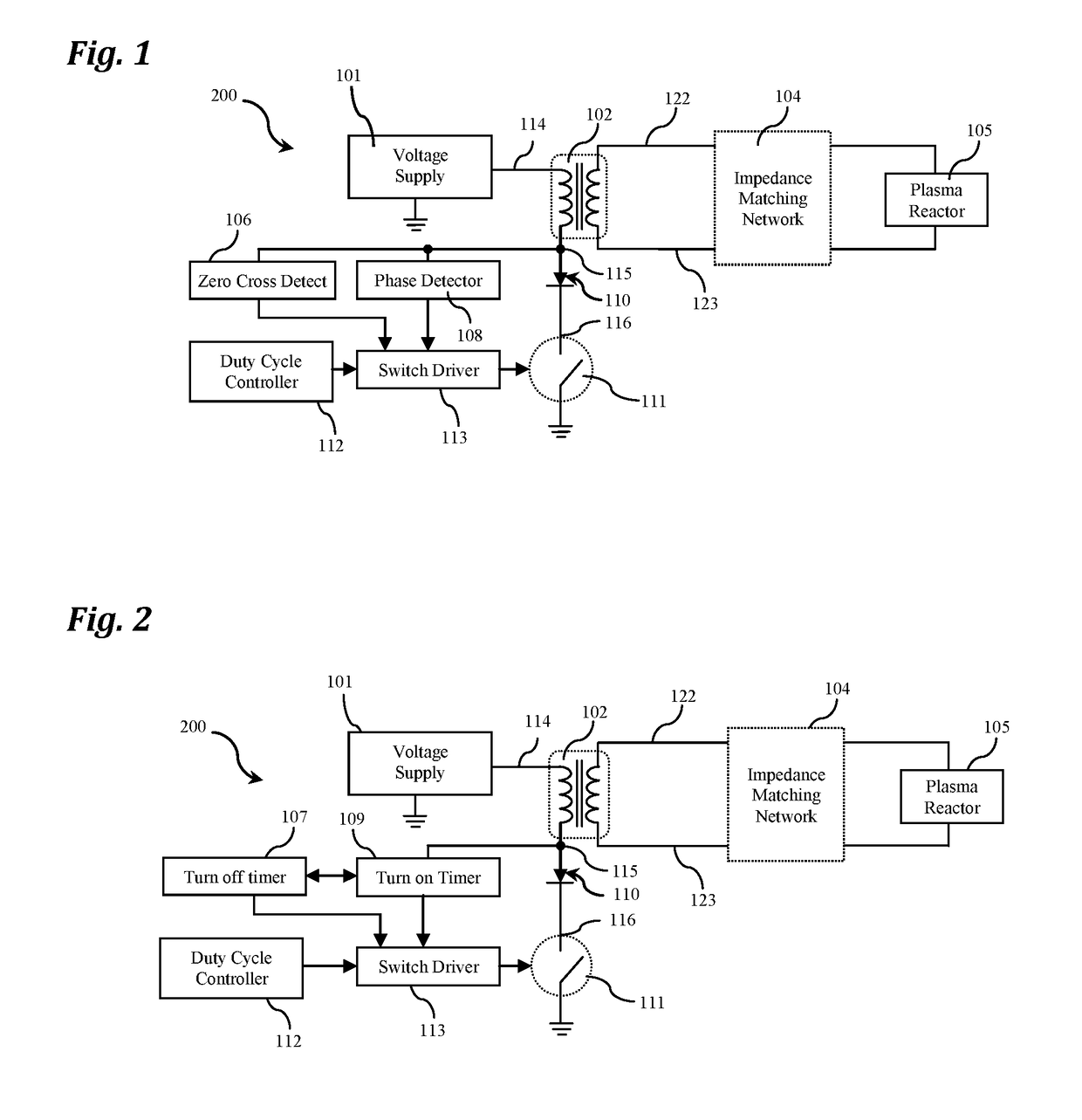
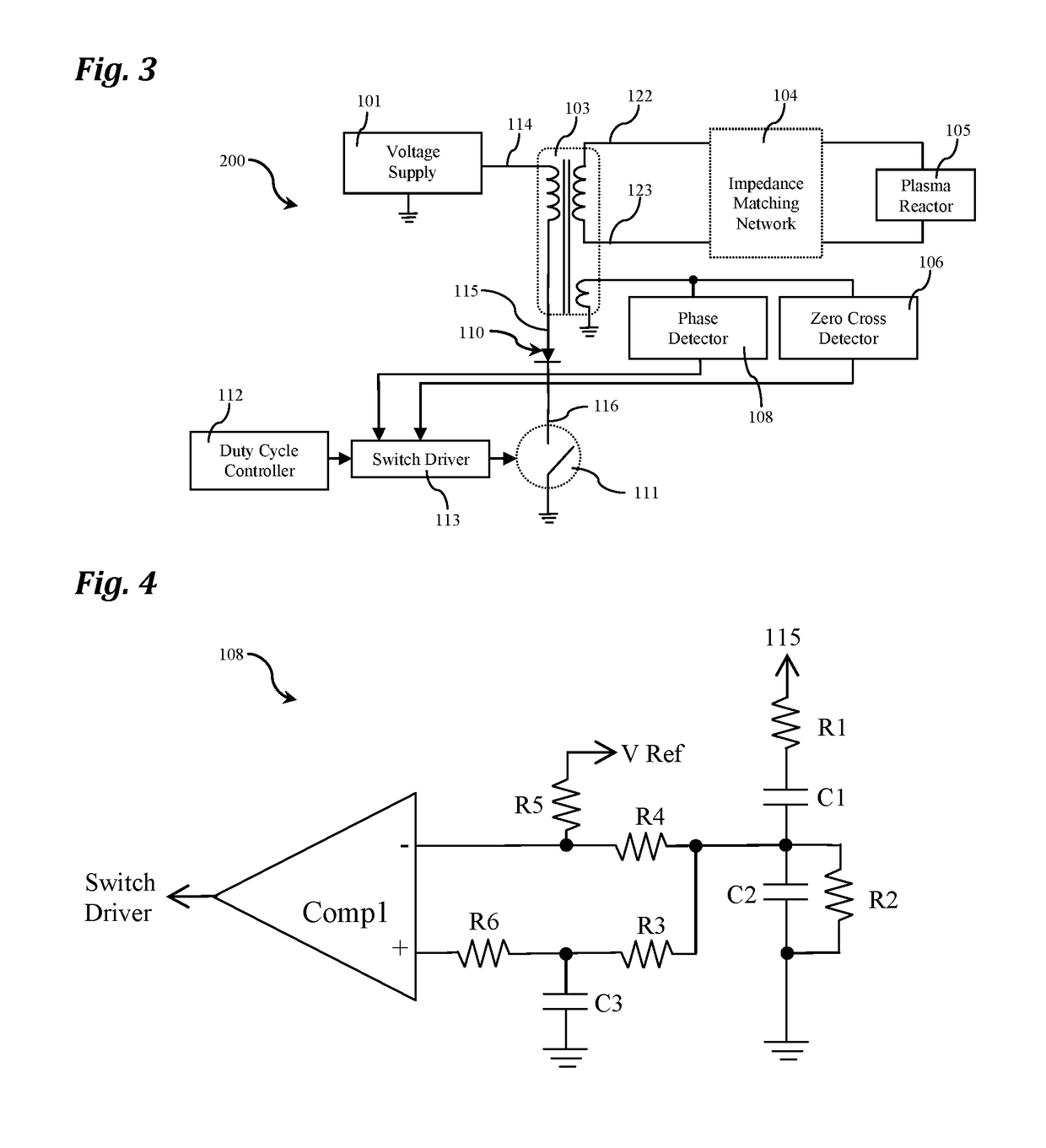
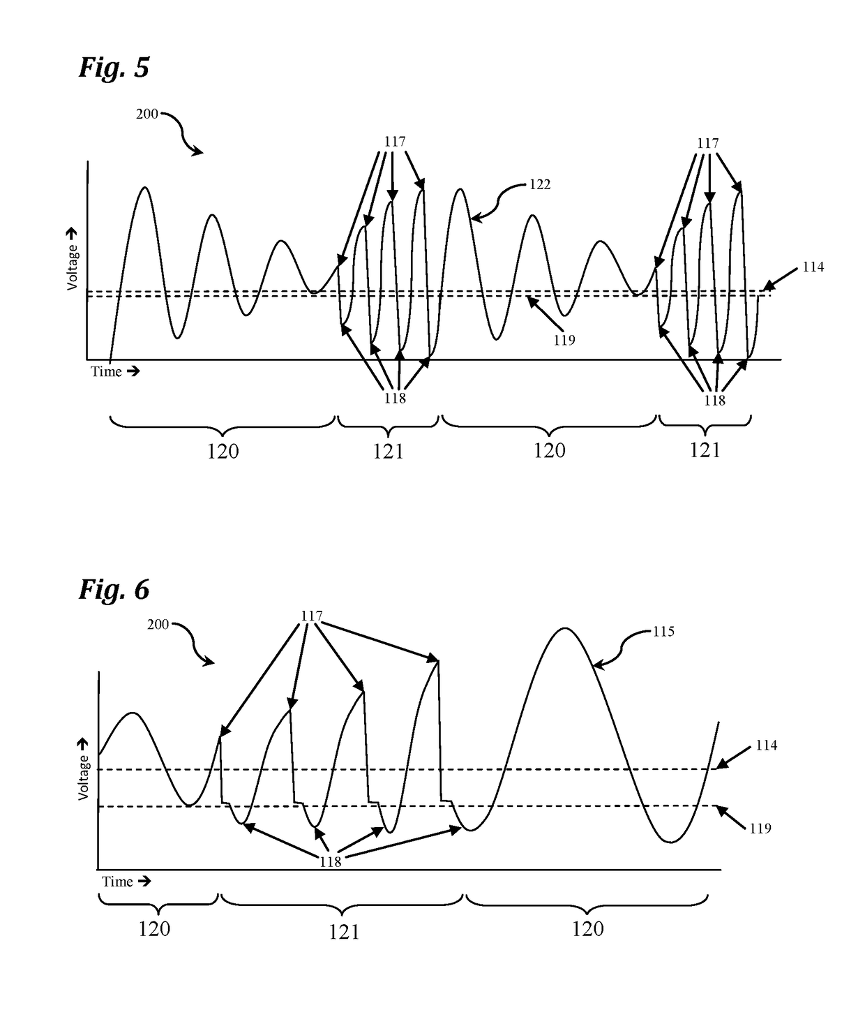
[0024]The following detailed description of the invention references the accompanying drawings that illustrate specific embodiments in which the invention can be practiced. The embodiments are intended to describe aspects of the invention in sufficient detail to enable those skilled in the art to practice the invention. Other embodiments can be utilized and changes can be made without departing from the scope of the current invention. The following detailed description is, therefore, not to be taken in a limiting sense. The scope of the current invention is defined only by the appended claims, along with the full scope of equivalents to which such claims are entitled.

[0025]In this description, references to “one embodiment”, “an embodiment”, or “embodiments” mean that the feature or features being referred to are included in at least one embodiment of the technology. Separate references to “one embodiment”, “an embodiment”, or “embodiments” in this description do not necessarily ref...


PUM


Abstract

Traditional plasma voltage generator circuits consist mainly of fly-back or pulse forming networks. These systems tend supply plasma generating pulses to plasma reactors at frequencies less than 30 kHz with most being less than 5 kHz. In addition these traditional plasma voltage generators are limited in the ability to adjust to dynamic reactor conditions, are energy inefficient and are limited in the amount of material ionized. An innovative drive system is presented herein that is energy efficient, can operate at frequencies below and well above 30 kHz, and can react to dynamic conditions in the plasma reactor allowing much greater flexibility and enhanced operating capabilities.

Description

FIELD OF INVENTION[0001]Embodiments of the current invention relate to plasma reactors and the driver electronics utilized to create high electric fields.BACKGROUND[0002]Plasma reactors may include at least two electrodes which are spaced apart. Typically, a voltage difference is applied to the electrodes and an electric field is established between them. A stream of gas, or multiple streams of different gasses, and or gasses and liquids, gasses and solids or other material or combinations of materials may be introduced to the space between the electrodes such that said materials partially or completely pass through the electric field. Exposure to the electric field generally partially or completely ionizes the gas and other materials between the electrodes and creates a plasma. The systems used to create the electric field which encourages the plasma to form are herein referred to as plasma voltage generators. This novel plasma voltage generator is relevant to many plasma reactors ...

Claims


Application Information

Patent Timeline
Patent Type & Authority Patents(United States)
IPC IPC(8): H05H1/46H05H1/00H03H7/38
CPCH05H1/46H05H1/0006H03H7/38H05H2001/4682H05H2242/26
Inventor BUCHANAN, WALTER RILEYFORSEE, GRANT WILLIAM
Owner MILTON ROY
Why Eureka
Try Eureka