Fog-generating device comprising a reagent and ignition means

a technology of fog-generating device and ignition means, which is applied in the direction of gas-blowing apparatus, single-unit apparatus, alarms with smoke/gas/colored powder, etc., can solve the problems of restricting the capacity of such pumps, too high product prices, and restricting the fog output of fog-generating devices, so as to increase the efficiency of fog generation, the construction and cost of the device are negligible, and the effect of reducing the turbulence of fog generating materials

Active Publication Date: 2019-01-29
BANDIT LLC
View PDF15 Cites 3 Cited by
  • Summary
  • Abstract
  • Description
  • Claims
  • Application Information

AI Technical Summary

Benefits of technology

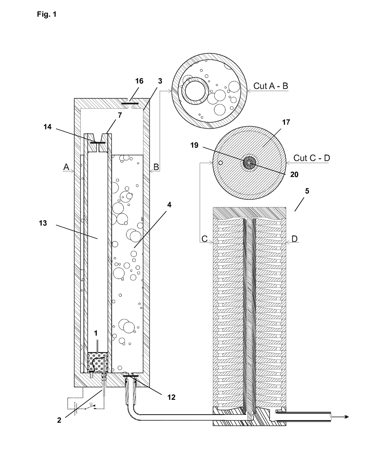
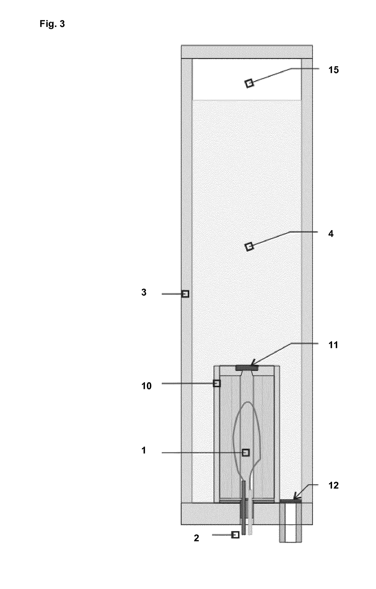
[0020]In another preferred embodiment, the fog-generating device of the present invention further comprises means (10 and 11, or 7 and 13) that separate the fog-generating material from the reagent. Such separation means prevent undesired contact between the fog-generating material the reagent and ignition means, e.g. due to movement or transport of the device. In particular when the fog-generating material is a liquid, separation means prevent wetting of the reagent and the ignition means. In one embodiment said separation means may be constructed so that they fully or partially disintegrate upon gas generation. As for example shown in FIG. 3, the reagent (1) could be confined in a housing (10) having a pressure and / or temperature sensitive closure (11). Upon ignition of the reagent and subsequent gas formation pressure and / or temperature will increase within said housing. Under influence of said pressure and / or temperature the pressure and / or temperature sensitive closure (11) will disintegrate releasing the generated gas into reservoir (3) containing the fog-generating material (4). In another embodiment, such as for example shown in FIG. 5, the separation means are movable and remain intact during and after gas generation. In such instance, movement of the separation means may lead to expelling fog-generating material from the reservoir. It is accordingly an object of the present invention to provide the use of a reservoir comprising separation means, in particular movable separation means, and a fog-generating material in a fog-generating device. In particular in a fog-generating device comprising a heat-exchanger.
[0021]More reagent can be added than is strictly necessary to drive the fog-generating fluid from the reservoir to the heat exchanger. Given that only minor amounts of reagent as described herein are needed to generate large volumes of gas, the effects of such an addition to the construction and cost of the device are negligible. However, it has been found that the extra energy produced by the gas generation can be used for several additional beneficial effects.
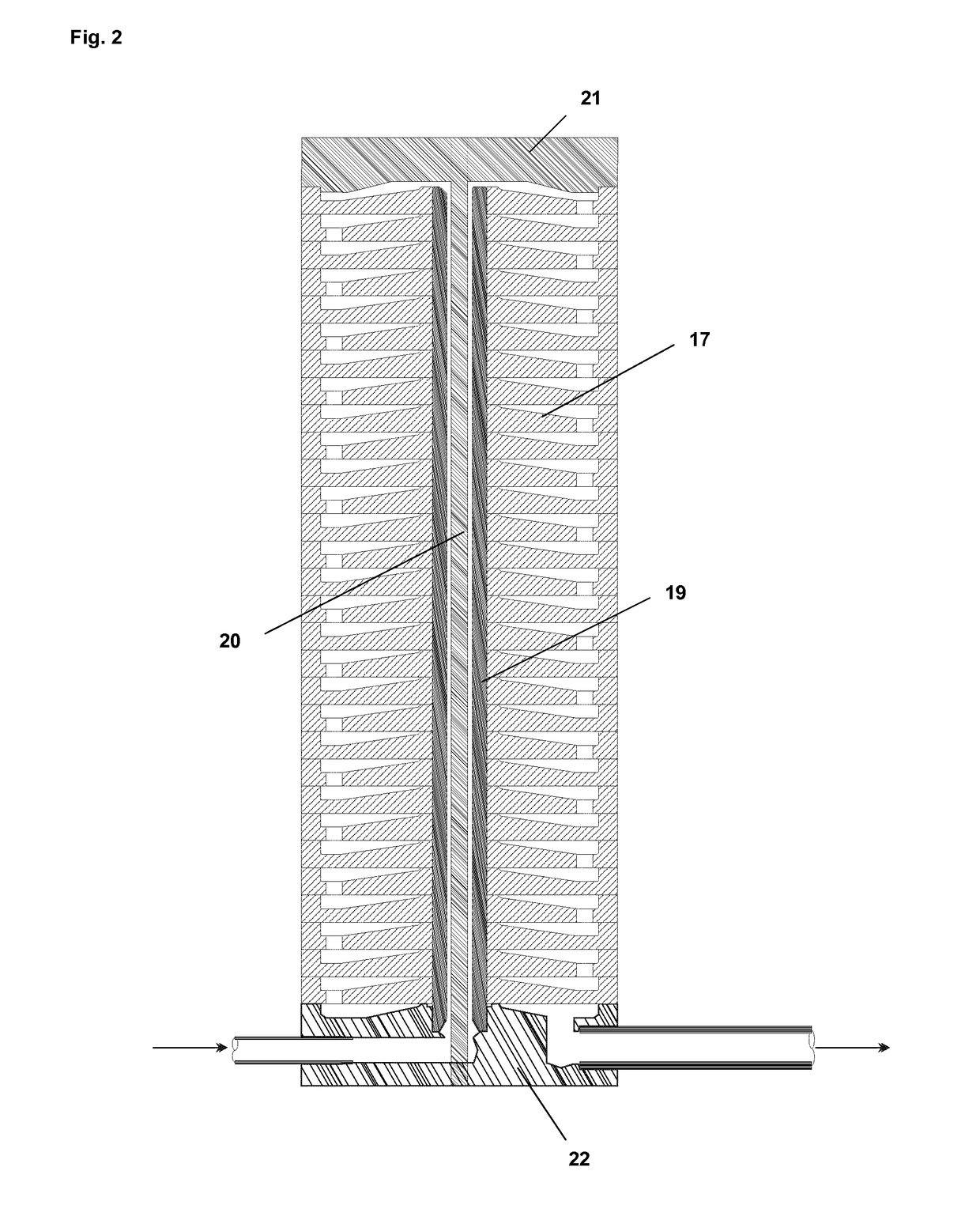
[0022]For example, larger volumes of gas may be mixed and dissolved into the fog-generating material before it enters the heat exchanger. Once inside the heat exchanger, this dissolved gas expands with the generation of gas bubbles, leading to higher turbulence of fog generating material. As such, with the amount of gas dissolved in the fog generating material, there is a better contact between the fog-generating material and the heat exchanger, which increases the efficiency of fog generation, and augments the energy content of expelled fog.
[0023]The higher energy of the expelled fog due to the additional generated gas can also be used to entrain ambient air into the expelled fog. Therefore, in another embodiment, the fog-generating device may further comprise means, such as a steam ejector, to entrain ambient air in the generated fog. The entrained ambient air has been found to result in a better dissipation of the fog into the surroundings.

Problems solved by technology

Fog-generating device are often powered by standard voltage batteries, further restricting the capacity of such pumps.
In addition, high-capacity liquid pumps would lead to too high product prices.
Therefore, utilization of pumps to drive fog-generating liquids from the reservoir to the heat-exchanger seriously restricts the fog output of those fog-generating devices.
When fog is generated too slowly, the thief may use the additional seconds to quickly grasp valuables before leaving.
While the pressure (P) and volume (V) that can be contained in the vessel is unlimited in theory, the legal framework on devices containing pressurized vessels restricts it's capacity.
Above certain pressure thresholds and P×V, the laws make it impractical to build, transport, install and use such devices.
Prior art fog-generating devices for security purposes have another inherent risk.
Indeed, it is very likely that a burglary / violent threat will only happen (if ever) several years after installment of the device.
It has been found that prior art fog-generating devices comprising pumps become unreliable over time, apparently due to blockage, corrosion and / or chemical resistance problems or other failure of these pumps when they are not regularly used.
Although the pump-less variant of WO2008132113 already presents an improvement in that regard, it is not possible to fully exclude that the switch that regulates the release of the fog-generating fluid from the pre-pressurized reservoir would become micro-leaking or defective.
Furthermore, prior art fog generators are often “one-shot” devices, which require that the device is refilled in situ by a skilled technician, or require that the device is sent to the manufacturer for refilling.
Especially for security purposes, it is not wanted that the device can not function for a substantial period until a technician has refilled it or until a replacement device has been sent and installed.
In addition, such a process is time-, resource- and cost-intensive.
Further problems often associated with the prior art devices are the limited degree of freedom for orienting the device.
Although orientation of the exit from where the fog is blown is often crucial, e.g. for concealing particular parts of the room in first instance, prior art devices don't allow much freedom as in certain positions the fog-generating device will simply not work, or fog-generating liquid will spill out of the reservoir, thereby damaging the device or leaving insufficient liquid in the reservoir for proper functioning.
However, it is very restricted in its orientation and tilting the device would result in absence of smoke production.
In addition, the device is a “one-shot” and would need complete replacement or cumbersome refilling in a factory.
Furthermore, smoke production will only be initiated after smoke fluid has been heated by a further pyrotechnic device, thereby slowing down the start of smoke exiting.
However, similar to U.S. Pat. No. 6,087,935, the smoke generator of EP0726550 can not be oriented in any direction and smoke fluid may flow out of the reservoir and wet the reagent.
Furthermore, the device is a “one-shot” device requiring replacement of the whole device after it functioned.

Method used


Image

  • Fog-generating device comprising a reagent and ignition means
  • Fog-generating device comprising a reagent and ignition means
  • Fog-generating device comprising a reagent and ignition means

Examples


Embodiment Construction

[0039]As discussed herein before, it has been found that the problems associated with the fog-generating devices of the prior art can be solved by the generation of a fog-generating device that comprises a reagent, ignition means, a reservoir containing a fog-generating material, and a heat exchanger characterized in that gas generated by ignition of the reagent drives fog-generating material from said reservoir to said heat exchanger. In a particular embodiment, said fog-generating device further comprises a movable wall and wherein gas generated by ignition of the reagent drives said movable wall to expel fog-generating material from said reservoir to said heat exchanger. In another particular embodiment, the present invention provides a removable housing for removably connecting to a fog-generating device that comprises a heat exchanger, said removable housing comprising at least a reservoir (3) containing a fog-generating material (4); in particular comprising a reagent (1) and ...


PUM

PropertyMeasurementUnit
flow rateaaaaaaaaaa
pressureaaaaaaaaaa
forceaaaaaaaaaa

Abstract

The present invention relates to a fog-generating device comprising a reagent (1), ignition means (2), a reservoir (3) containing a fog-generating material (4), and a heat exchanger wherein gas generated by ignition of the reagent (1) drives fog-generating material from said reservoir to said heat exchanger. Further it relates to a removable housing for a fog-generating device comprising a reagent and a reservoir containing a fog-generating material, wherein in that said removable housing further comprises means to allow transmission of an ignition signal from said fog-generating device to said reagent. The invention further provides the use of said device and / or removable housing for the generation of fog, in particular to protect against intruders and physical treat by persons. In a particular embodiment, the fog-generating device of the present invention or the removable housing therefore comprises depressurizing means (18). Depressurizing means allow the escape of gas from the device so that the pressure inside the device is reduced and becomes closer to atmospheric pressure.

Description

FIELD OF THE INVENTION[0001]The present invention relates to a fog-generating device comprising a reagent, ignition means, a reservoir containing a fog-generating material, and a heat exchanger wherein gas generated by ignition of the reagent drives fog-generating material from said reservoir to said heat exchanger. Further it relates to a removable housing for a fog-generating device comprising a reagent and a reservoir containing a fog-generating material, wherein in that said removable housing further comprises means to allow transmission of an ignition signal from said fog-generating device to said reagent. The invention further provides the use of said device and / or removable housing for the generation of fog, in particular to protect against intruders and / or physical treat by persons. It further provides the use of the removable housing in its different embodiments as described herein, in a fog-generating device. It also provides the use of a reservoir comprising a movable wal...

Claims


Application Information

Patent Timeline
Patent Type & Authority Patents(United States)
IPC IPC(8): B05B9/00F41H9/04G08B15/02C06D3/00B05B1/24B05B11/02B05B11/00B05B7/16A63J5/02
CPCC06D3/00A63J5/025B05B1/24B05B7/166G08B15/02B05B9/002B05B11/0005B05B11/02F41H9/04B05B7/1666
Inventor VANDONINCK, ALFONS
Owner BANDIT LLC
Why Eureka
Try Eureka