Supercharge Your Innovation With Domain-Expert AI Agents!

Power storage system, power storage module, and control method

a power storage module and power storage technology, applied in the direction of emergency power supply arrangement, dc-ac conversion without reversal, safety/protection circuit, etc., can solve problems such as system damage, and achieve the effect of reducing rush curren

Active Publication Date: 2019-01-29
MURATA MFG CO LTD
View PDF19 Cites 2 Cited by
  • Summary
  • Abstract
  • Description
  • Claims
  • Application Information

AI Technical Summary

Benefits of technology

The patent system uses a battery as a power supply and has a feature that helps reduce the sudden surge of power needed when starting up. This feature is helpful in maintaining the battery's lifespan and ensuring that it runs smoothly. However, the patent doesn't limit what other benefits can be achieved using this system.

Problems solved by technology

However, a large current (rush current) may flow through the system when the units are connected during operation of the system and the system may be damaged.

Method used


Image

  • Power storage system, power storage module, and control method
  • Power storage system, power storage module, and control method
  • Power storage system, power storage module, and control method

Examples


embodiment

1. Embodiment

Example of Configurations of General Power Storage System and Power Storage Module

[0029]For easy understanding of the present technology, examples of general power storage system and power storage module will first be described.

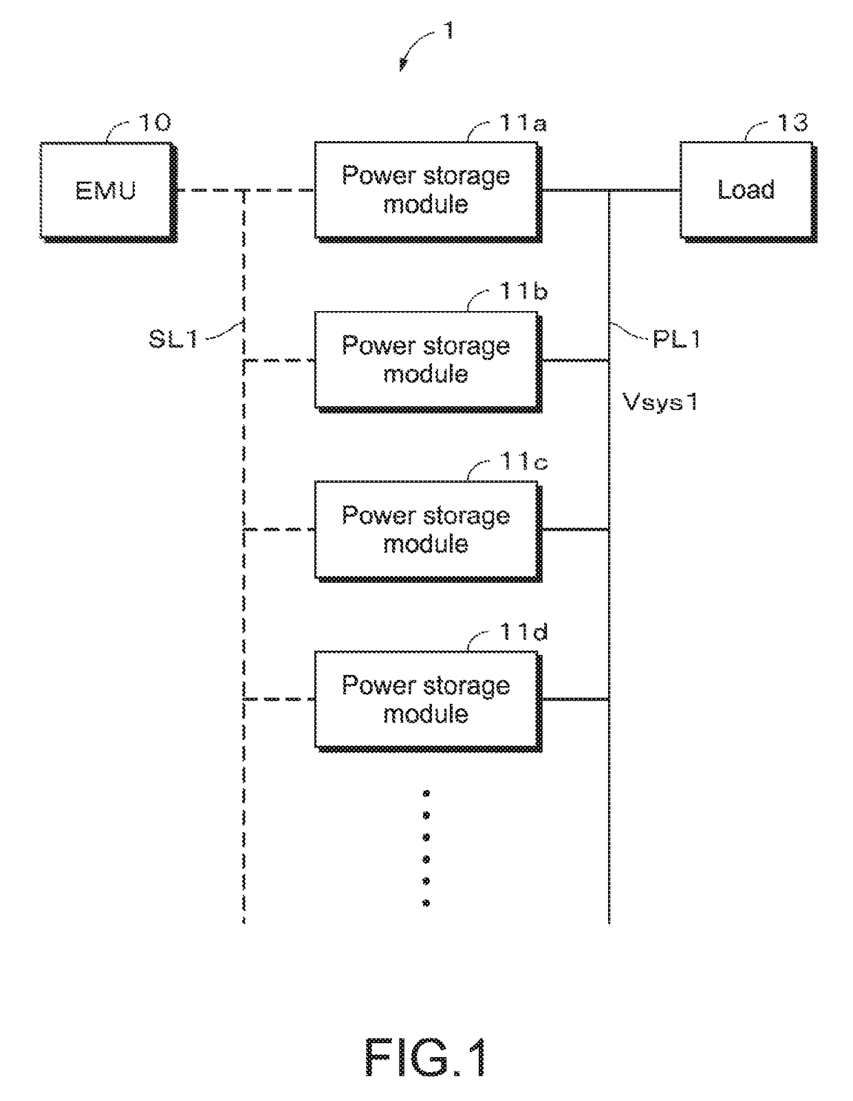
[0030]FIG. 1 is a diagram for describing an example of the configuration of the general power storage system. A power storage system 1 includes an EMU (Energy Management Unit) 10 and a plurality of power storage modules. FIG. 1 shows a power storage module 11a, a power storage module 11b, a power storage module 11c, and a power storage module 11d as examples of the plurality of power storage modules. When it is not necessary to distinguish the power storage modules, they will be referred to as power storage modules 11.

[0031]The EMU 10 and the power storage modules 11 are connected to one other via a predetermined communication line SL1. Data and commands can be exchanged between the EMU 10 and the power storage modules 11 via the communication li...

application examples

3. Application Examples

[0128]Application examples of the present technology will be described. Note that the contents of the present technology are not limited to the application example described below.

[0129]“Power Storage Apparatus in House as Application Example”

[0130]An example in which the present technology is applied to a power storage apparatus for a house will be described referring to FIG. 8. For example, in a power storage apparatus 100 for a house 101, power is supplied from a centralized power system 102 such as a thermal power generation 102a, a nuclear power generation 102b, and a hydroelectric power generation 102c to a power storage apparatus 103 via a power network 109, an information network 112, a smart meter 107, a power hub 108, or the like. Along with this, power is supplied from an independent power supply such as a private power generation apparatus 104 to the power storage apparatus 103. The power supplied to the power storage apparatus 103 is stored. Using...


PUM


Abstract

[Solving Means] A power storage system includes, for example, a plurality of power storage modules connected in parallel to a power line and a system voltage acquisition unit that obtains a system voltage in the power line. The power storage module includes a power storage section formed of one or more storage batteries and a current control unit that controls a current that flows between the power storage section and the power line. The current control unit controls, according to the system voltage and a voltage of the power storage section, the current that flows between the power storage section and the power line.

Description

TECHNICAL FIELD[0001]The present technology relates to a power storage system, a power storage module, and a control method.BACKGROUND ART[0002]A technique relating to so-called hot swapping, for example, exchanging, removing, or adding units that constitute a system during operation of the system is known. However, a large current (rush current) may flow through the system when the units are connected during operation of the system and the system may be damaged. Therefore, reducing the rush current has been proposed (e.g., see Patent Document 1 below).[0003]Patent Document 1: Japanese Patent Application Laid-open No. HEI09-284998SUMMARY OF INVENTIONProblem to be Solved by the Invention[0004]The technique of Patent Document 1 does not use a battery as a power supply. Also in a system using the battery as the power supply, it is desirable to reduce the rush current.[0005]Therefore, it is an object of the present technology to provide a power storage system, a power storage module, an...

Claims


Application Information

Patent Timeline
Patent Type & Authority Patents(United States)
IPC IPC(8): H02J3/38H02J7/00H02J7/34H02M7/06H02M7/44H02J7/35H02J9/06
CPCH02J3/383H02J7/0031H02J7/0063H02J7/0068H02J7/34H02J7/35H02M7/06H02M7/44H02J9/062Y02E10/566H02J2007/0039Y02B10/72Y02E10/563H02J7/00304H02J2300/24H02J3/381Y02B10/70Y02E10/56H02J7/007
Inventor SEKITA, SUGURU
Owner MURATA MFG CO LTD
Features
  • R&D
  • Intellectual Property
  • Life Sciences
  • Materials
  • Tech Scout
  • Unparalleled Data Quality
  • Higher Quality Content
  • 60% Fewer Hallucinations
Learn More