
Optical scanner and scanned lens optical probe

a technology which is applied in the field of optical scanner and optical probe, can solve the problems of dimmer objects, low signal to noise ratio, and optical systems optimized for on-axis imaging that are not simultaneously optimized for off-axis imaging, and achieves the effect of reducing or eliminating lateral chromatic shift and high speed

Active Publication Date: 2019-02-05
OPTISCAN
View PDF5 Cites 1 Cited by
  • Summary
  • Abstract
  • Description
  • Claims
  • Application Information

AI Technical Summary

Benefits of technology

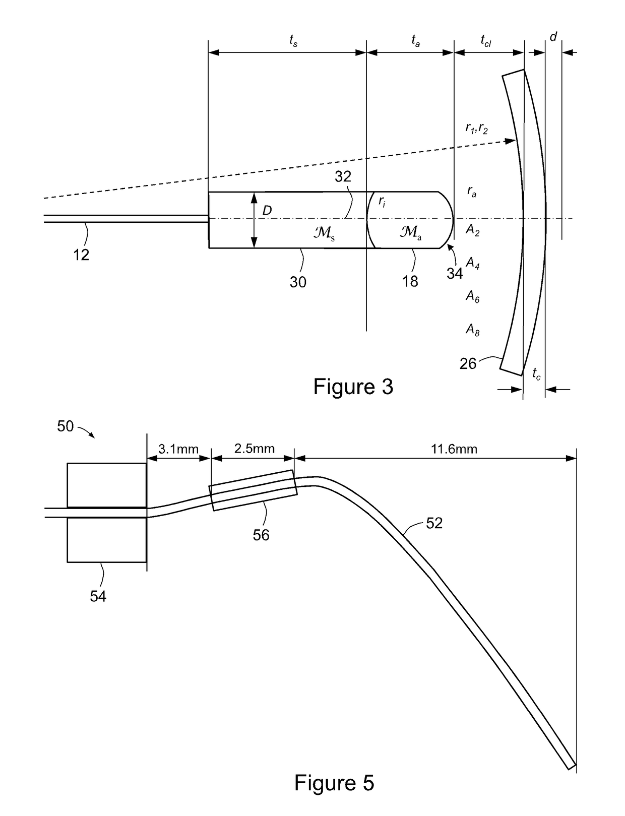
[0012]Thus, the lens group breaks down the traditional trade-off between field of view and numerical aperture, as it allows one to have high values of both these parameters, and also allows the minimization or elimination of lateral chromatic shift, by keeping the relative geometry of the lens group, imaged specimen and coverslip the same as the on-axis geometry throughout a scan.
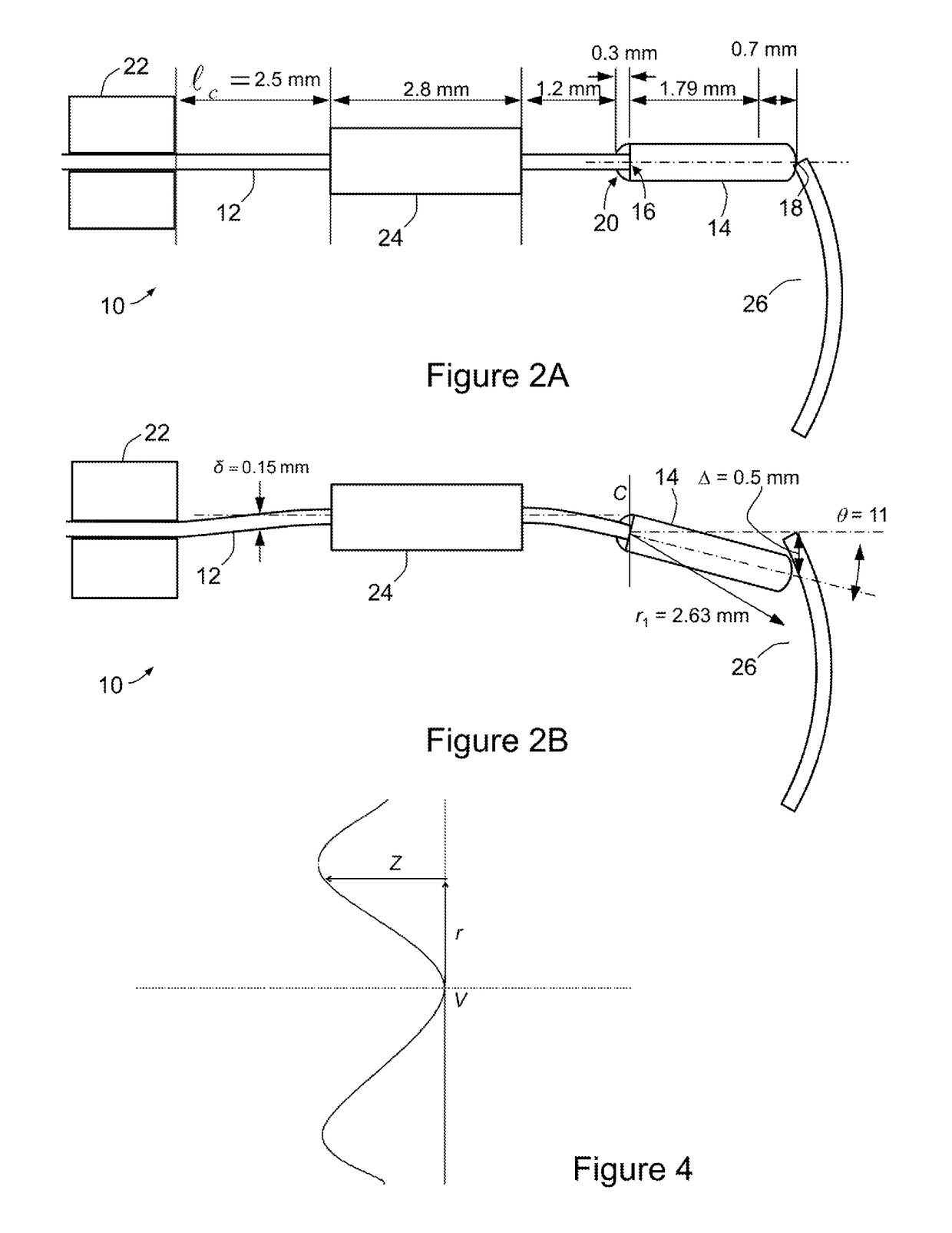
[0013]The lens group may be provided in a scanner that is very small and light whilst being highly optically corrected both for aberration and for chromatic shift (either “actively” or “passively”, as described below); a bare optical waveguide (e.g. an all glass, conventional optical fibre with no specialised sheathing or other stiffness / inertia modifying device) can be used so that the lens system can be miniaturised enough and scanned at high speed (i.e. at resonant frequencies an order of magnitude faster than the 150 Hz referred to in some of the background art). The lens group may be bonded directly to the (scanning) optical waveguide with essentially no airgap between the optical waveguide and first element of the waveguide, which makes for simplicity in construction and allows active alignment to be readily performed.
[0014]The present invention allows the construction of a “Universal” probe that allows simultaneous one-photon and two-photon imaging with effectively any number of fluorophores whilst bringing all wavelengths to the same focus to within 2 μm over a 450 nm to 850 nm spectrum and numerical apertures up to 0.5 NA, and possibly as high as 0.7 NA. Moreover, this chromatic correction provides two-photon imaging performance better than the background art discussed above.
[0018]In one embodiment, the lens group has a chromatic shift that is highly corrected such that an input light wavepacket of less than a picosecond pulse width and centred at a wavelength of the driving light is only slightly broadened in pulse width when passing through the lens group (so that the loss of peak pulse intensity and two-photon coupling efficiency is small), thus making the system particularly fit for many-photon imaging). For example, a loss of less than 1 dB would be desirable, but a lens group (or system provided therewith) with a 2 dB or a 3 dB loss would also be valuable.
[0032]In still another embodiment, the lens group comprises a plurality of lens elements (of like or unlike glasses) glued or otherwise bonded together after manufacture, typically by machining. This allows them to be readily built by lens making CNC robots, which otherwise tend to shatter lenses whose side profile is too long and thin.
[0050]In the optical system of the second and third aspects, the optical waveguide may further comprise one or more auxiliary lightguiding cores, so that the imaging numerical aperture can be switched between the main, high resolution value to a low value (say 0.1 NA), possibly with in-between steps to allow the user to position the image easily, with coarse axial resolution and high tolerance to siting errors and hand unsteadiness and then switch to a high resolution mode (with lower tolerance) once the target tissue has been identified.

Problems solved by technology

In general, the further an object is from the centre of an optical system's optical axis, the worse the imaging system's Strehl ratio is and thus the dimmer the object will appear and the worse will be its signal to noise ratio.
Practical optical systems that are optimized for on-axis imaging are not simultaneously optimized for off-axis imaging.
The concatenation of ten optical elements in turn makes it costly to achieve the required stringent optical quality and mechanical tolerances.
A further problem with these systems is the low numerical aperture of the output field of the fibre.
However, the system of US 2011 / 0211104 includes several electrical channels running along a scanning steel tube that couples the first lens to the optical guide, employs large, heavy lenses and does not address the problem of chromatic aberration (other than to calculate the pulse spread for many-photon imaging).

Method used


Image

  • Optical scanner and scanned lens optical probe
  • Optical scanner and scanned lens optical probe
  • Optical scanner and scanned lens optical probe

Examples


example 1

ally Uncorrected 0.26 NA System “Uncorrected 0.40 / 0.26 NA”

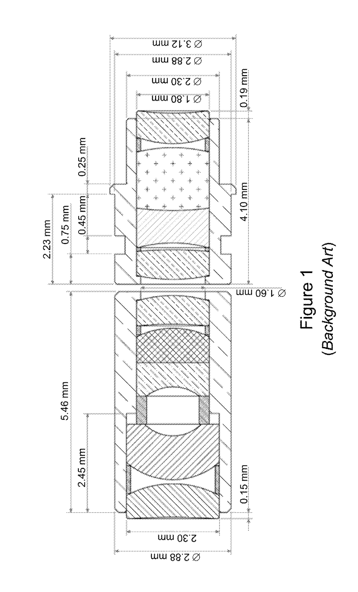
[0128]FIG. 6 is a schematic view of a lens group 60 suitable for use in a scanner such as optical system 10, shown with a window or coverslip 68, a tissue specimen 69 and rays for a 0.095 NA input from a lightguide. This design assumes that the focus is 50 or 99 μm deep into specimen 69 (see “Nominal imaging depth” in Table 1). Lens group 60 constitutes an 0.26 NA uncorrected system, and is adapted for FITC (fluorescein isothiocyanate) one photon fluorescence confocal imaging with FITC as the fluorophore; hence, the driving wavelength is 488 nm and the fluorescence returns in a band stretching from roughly 520 nm to 550 nm with a 532 nm fluorescence peak wavelength. The optical performance is designed to be slightly better than that of a bulk optic system of the type shown in FIG. 1. Lens group 60 has a substrate 62 of Schott (trade mark) N-SF66 and the aspheric lens 64 of Ohara (trade mark) L-LAM60, which meet at a panar int...

example 2

ally Uncorrected 0.30 NA System “Uncorrected 0.47 / 0.30NA”

[0129]FIG. 7 is a schematic view of a lens group 70, shown with a window or coverslip 78 and a tissue specimen 79. This example is also suitable for use in a scanner such as optical system 10, being adapted for FITC one photon fluorescence confocal imaging but with optical performance significantly better than that of the bulk optic system of FIG. 1. Its shorter length and higher magnification makes it slightly more sensitive to manufacturing imperfections (discussed below). Lens group 70 comprises a substrate 72 of Ohara S-NPH2 and an aspheric lens 74 of Schott L-LAM60; substrate 72 of Ohara S-NPH2 yields slightly better partial chromatic correction at the higher numerical aperture.

[0130]This numerical aperture is approximately the highest that is worth striving for with an uncorrected system of this sort, because the axial responses (i.e. the maximum intensity of the focussing light in a given plane of constant axial positio...

example 3

omatically Corrected 0.33 NA System “Universal 0.50 / 0.33NA”

[0132]FIG. 8 is a schematic view of a lens group 80, shown with a window or coverslip 88 and a tissue specimen 89. This example is also suitable for use in a scanner such as optical system 10, and comprises a substrate 82 of Ohara S-NPH2 and an aspheric lens 84 Ohara L-LAM60, which meet at a spherical interface 86. Lens group 80 is adapted to transmit light at wavelengths between 450 nm and 850 nm to essentially the same focus, to within a micron, owing to the opposite wavelength variations for the optical powers from spherical interface 86 on the one hand and the aspherical interface 87 between the Ohara L-LAM60 glass of aspheric lens 84 and freespace at the distal tip of lens group 80.

[0133]As a result, lens group 80 can be used for a variety of many-channel one-photon or two photon fluorescence / reflection confocal microscopy or endoscopy systems. Arbitrarily many drive wavelengths in the band 450 nm to 850 nm can be used;...


PUM

PropertyMeasurementUnit
fluorescence wavelengthaaaaaaaaaa
wavelengthaaaaaaaaaa
frequencyaaaaaaaaaa

Abstract

A lens group for an endoscope or microscope, comprising one or more lens elements, each of uniform refractive index, adapted to: i) focus, with high wavefront aberration correction, driving or excitation light received from an exit tip of an optical waveguide (such as an optical fiber) located substantially against a proximal surface of the lens group to a point observational field with narrow point spread function beyond a distal surface of the lens group (such as outside an optical window located distally relative to the distal surface); and ii) transmit, with high wavefront aberration correction, fluorescence or reflected return light received by the distal surface from the point observational field (and its neighborhood defined by the fluorescence wavelength point spread function) back to the exit tip of the optical waveguide at the fluorescence wavelength.

Description

FIELD OF THE INVENTION[0001]The present invention relates to a optical scanner and scanned lens optical probe, of particular but by no means exclusive application as a microscope, endoscope or endomicroscope.BACKGROUND OF THE INVENTION[0002]In general, the further an object is from the centre of an optical system's optical axis, the worse the imaging system's Strehl ratio is and thus the dimmer the object will appear and the worse will be its signal to noise ratio. Moreover, there is a trade-off between field of view and numerical aperture: the higher the numerical aperture of an optical system is (i.e. the smaller the object it can resolve), the smaller is the field of view over which the system's Strehl ratio is acceptably large (particularly for in vivo systems), and over which vignetting is acceptably small. This trade-off arises from the change of the relative geometry of the imaging optics, the object and the object's image as the position of an object changes in the field of ...

Claims


Application Information

Patent Timeline
Patent Type & Authority Patents(United States)
IPC IPC(8): A61B1/04G01N21/64G02B27/42G02B21/00G02B26/10A61B1/00G02B13/18G02B23/24A61B1/07
CPCA61B1/043A61B1/00096A61B1/00172A61B1/00188A61B1/07G01N21/6458G02B21/0076G02B23/2476G02B26/103G02B27/425G02B27/4211G02B27/4216G02B13/18G01N2021/6478
Inventor VANCE, RODERICK WILLIAM CHARLES
Owner OPTISCAN
Learn More