Power transmission system for vehicle

a transmission system and vehicle technology, applied in the direction of positive displacement liquid engines, vehicle sub-unit features, gearing, etc., can solve the problem of not being able to accurately measure the oil temperature inside the transaxle case, and achieve the effect of avoiding unnecessary erroneous determination

Active Publication Date: 2019-02-05
TOYOTA JIDOSHA KK
View PDF38 Cites 3 Cited by
  • Summary
  • Abstract
  • Description
  • Claims
  • Application Information

AI Technical Summary

Benefits of technology

[0007]The embodiment provides a power transmission system that is able to correctly measure an oil temperature inside a transaxle since oil circulates even when a check valve installed in an electric oil pump is stuck, and to reduce erroneous determination in determining whether there is a fault in the electric oil pump.
[0009]According to the aspect of the embodiment, by providing the third check valve in parallel with the first check valve connected to the electric oil pump, oil circulates even when the first check valve is stuck. Thus, it is possible to correctly detect an oil temperature inside a transaxle case with the use of the oil temperature sensor downstream of the third check valve.
[0011]With the above configuration, the flow resistance of the oil passage in which the third check valve is provided is set so as to be larger than the flow resistance of the oil passage in which the first check valve is provided, so, when a load larger than usual is exerted on the electric oil pump in a state where the first check valve is stuck, the rotation speed of the electric oil pump becomes lower than usual. Thus, it is possible to vary the rotation speed of the electric oil pump for the same oil temperature between a normal state and a stuck state, so it is possible to determine a stuck abnormality.
[0015]With the above configuration, there is provided means for determining that there is an inconvenience in the electric oil pump or the oil passage in which the first check valve is provided when the rotation speed of the electric oil pump is lower than the predetermined rotation speed, the predetermined rotation speed is a rotation speed higher than the rotation speed of the electric oil pump for an oil temperature detected by the temperature sensor at the time when the first check valve is not open, the third check valve is open, the electric oil pump normally operates and oil is being normally supplied through the third check valve, and the predetermined rotation speed is a rotation speed lower than the rotation speed of the electric oil pump for an oil temperature detected by the temperature sensor at the time when the first check valve is open, the electric oil pump normally operates and oil is being normally supplied through the first check valve. When a temperature detected by the oil temperature sensor is different from an actual oil temperature, for example, when a temperature detected by the temperature sensor is higher than an actual temperature, it is not determined as fault conditions when the rotation speed exceeds a predetermined rotation speed for the detected oil temperature. When a temperature detected by the temperature sensor is lower than an actual temperature, it is determined as fault conditions when the rotation speed is lower than or equal to the predetermined rotation speed, so it is not erroneously determined as normal conditions. Therefore, by carrying out the above-described determination, it is possible to avoid unnecessary erroneous determination due to variations, or the like, in temperature detected by the oil temperature sensor.

Problems solved by technology

However, when the check valve installed in the electric oil pump is stuck, circulation of oil is impeded, so there is an inconvenience that it is not possible to accurately measure an oil temperature inside the transaxle case.

Method used


Image

  • Power transmission system for vehicle
  • Power transmission system for vehicle
  • Power transmission system for vehicle

Examples


Embodiment Construction

[0025]Hereinafter, an embodiment will be described in detail with reference to the accompanying drawings.

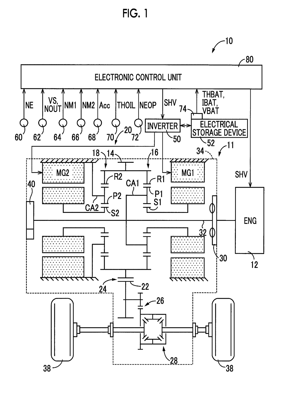
[0026]FIG. 1 is a view that illustrates the schematic configuration of a vehicle power transmission system 11 (hereinafter, referred to as power transmission system 11) of a hybrid vehicle 10 (hereinafter, referred to as vehicle 10) to which the embodiment is applied, and is a view that illustrates an electronic control unit (ECU) 80 provided in order to control portions of the power transmission system 11. As shown in FIG. 1, the power transmission system 11 includes a transmission unit 20. The transmission unit 20 includes a power distribution mechanism 16, a gear mechanism 18 and a second electric motor MG2. The power distribution mechanism 16 distributes power, which is output from an engine 12, to a first electric motor MG1 and an output gear 14. The engine 12 serves as a driving force source for propelling the vehicle 10. The gear mechanism 18 is coupled to the output gear ...


PUM


Abstract

By providing an auxiliary check valve in parallel with a check valve installed in an electric oil pump, it is possible to measure an oil temperature even when the check valve is stuck. A flow resistance of an oil passage of the auxiliary check valve is set so as to be larger than that of the check valve, and a minimum valve open pressure difference of the auxiliary check valve is set so as to be smaller than that of the check valve. Thus, it is possible to further accurately measure an oil temperature and determine a fault. By using a rotation speed of the electric oil pump and an oil temperature in determining whether there is a fault in the electric oil pump or in the oil passage, it is possible to reduce the influence of variations, or the like, in measurement of a temperature sensor.

Description

INCORPORATION BY REFERENCE[0001]The disclosure of Japanese Patent Application No. 2015-240645 filed on Dec. 9, 2015 including the specification, drawings and abstract is incorporated herein by reference in its entirety.BACKGROUND[0002]1. Technical Field[0003]The embodiment relates to a power transmission system for a vehicle and, more particularly, to a technique for enabling measurement of the temperature of oil for lubrication and cooling even when there occurs a fault in a check valve provided in an electric oil pump.[0004]2. Description of Related Art[0005]For example, there is known a vehicle, such as a hybrid vehicle. The vehicle includes an electric oil pump and a mechanical oil pump that are provided in an oil passage in parallel with each other. The electric oil pump operates by electric power supplied. The mechanical oil pump is directly driven by an engine to rotate. In the vehicle, oil is supplied from one of those electric oil pump and mechanical oil pump to a power tra...

Claims


Application Information

Patent Timeline
Patent Type & Authority Patents(United States)
IPC IPC(8): F16H57/04B60K6/365B60K6/44B60K6/543F16H3/72
CPCF16H57/0435F16H57/0441F16H57/0442F16H57/0476B60K6/365B60K6/44Y10S903/918B60Y2200/92B60Y2306/03F16H3/728F16H2200/2007Y10S903/911B60K6/543F04B49/103B60K6/445Y02T10/62
Inventor NISHIMINE, AKIKO
Owner TOYOTA JIDOSHA KK
Why Eureka
Try Eureka