Method for planning and designing debris flow drainage channels and applications thereof

a technology of debris flow and drainage channel, applied in the direction of artificial water canals, dykes, construction, etc., can solve the problems of increasing damage, increasing the flow velocity of debris flow at the upper increasing the flow velocity of debris flow at the lower end of the main channel, so as to maintain the safe operation of the drainage channel, prevent severe erosion, and efficiently drain the debris flow downstream

Inactive Publication Date: 2019-02-12
INST OF MOUNTAIN HAZARDS & ENVIRONMENT CHINESE ACADEMY OF SCI
View PDF9 Cites 2 Cited by
  • Summary
  • Abstract
  • Description
  • Claims
  • Application Information

AI Technical Summary

Benefits of technology

[0005]To address the current problem of lacking reasonable planning and design in the construction of a drainage channel, this invention provides a method for planning and designing debris flow drainage channels. This method is implemented by scientifically planning the composition of a debris flow drainage channel and reasonably selecting the channel type for the main channel. In particular, to construct a drainage channel on a long debris flow accumulation fan with a length of over 300 meters, it is proposed that the flow velocity of a debris flow be regulated by using an inter-channel transitional zone to efficiently drain the debris flow downstream via the drainage channel, thus avoiding the severe erosion and deposition of the debris flow in the drainage channel and thereby maximizing protection of the protected objects on the deposited fans.
[0016]Regulating the flow velocity of a debris flow refers to determining the limited flow velocity of a drainage channel based on the material and structure of the drainage channel. For a cement-rubble structure, the limited flow velocity is 6 m / s; for a concrete structure or a reinforced concrete structure, the limited flow velocity is 8 m / s; and for a steel fiber reinforced concrete structure, the limited flow velocity is 10 m / s. To maximize the drainage efficiency of the drainage channel, the designed flow velocity v2 of the downstream cross-section of the acceleration section and the designed flow velocity of the main channel section are 0.8-1.0 times as large as the limited flow velocity.
[0018]When the length of a debris flow-deposited fan is greater than 300 m, from upstream to downstream, at least two debris flow drainage channels that are relatively independent, connected in an end-to-end mode, and constructed according to the method for planning and designing are arranged, and the upstream part of the inlet section of the farthest upstream drainage channel is provided with a check dam used with the drainage channel. A transition zone is arranged between the upstream and downstream drainage channels and is used to accommodate the afflux of a debris flow or a torrential flood in a tributary ditch on the surface of the fan or is used to lead out part of the debris flow to prevent depositing. For a situation in which a drainage channel is constructed on a long deposited fan, according to the longitudinal slope of the gully bed of the long deposited fan, sectional and relatively independent short channels are arranged on the long deposited fan, such that each short channel comprises an inlet section, an acceleration section, a main channel section and an outlet section, and the longitudinal slope of the gully bed of each independent short channel and the channel type of the main channel section are separately determined. A transition zone is arranged at an engaged part between two short channels that can accommodate the afflux of debris flows or floods in other tributary ditches on the surface of the fan. Due to the changes in the longitudinal slope of the gully bed, for a situation in which the drainage capacity of the lower end is reduced, part of the debris flow can be directed out to prevent depositing (connected with a stop and deposit field through an overflow port arranged on the transitional zone) so that local deposits are eliminated, thereby maintaining the safe operation of the drainage channel. The long deposited fan is divided into multiple short channels, and each channel bodies are relatively independent, thereby avoiding a situation in which one short channel bursts and the entire channel is consequently destroyed.
[0019]Compared with the prior method, this invention has the beneficial effect that the characteristics of debris flow movement in the drainage channel are fully used and that based on regulating the moving flow velocity of a debris flow, the channel type of the main channel is reasonably selected. To construct a drainage channel on a debris flow-deposited fan with a length of over 300 meters, the long drainage channel is divided into multiple short drainage channels, and a transition zone for regulating the flow velocity of a debris flow is arranged between the sides of the channel to efficiently drain the debris flow downstream, thus preventing the severe erosion and deposition of the debris flow in the drainage channel, providing the maximum guarantee for protected objects on both sides of the drainage channel, and reducing the costs of engineering operating and maintenance.

Problems solved by technology

Due to the severe erosion produced by debris flow movement, a gully bed undergoes severe changes that can cause bottom tearing of the gully bed and the collapse of a gully bank, adding solid matter sources that replenish the debris flow, thereby increasing the damage it causes.
The integrally single channel type structure easily causes problems that the flow velocity of the debris flow at the upper end of the main channel increases too slowly and the flow velocity of the debris flow at the lower end of the main channel is too fast, so that the upper end of the drainage channel is deposited and the downstream part of the drainage channel is eroded.
On the other hand, for a long accumulated fan (length over 300 meters), currently, the same drainage channel is adopted to drain the debris flow generally, which causes defects because it is difficult to adapt the drainage channel to the great changes in the longitudinal slope of a gully bed in a long deposited fan.
An overlong drainage channel is not beneficial to the stability of a entire drainage system.
For example, after the upper end of a fully lined drainage channel with a length of 750 meters at the Shiwei River in Yunlong County of Yunnan Province was subject to bottom tearing, chain bottom tearing of the drainage channel occurs, and consequently the entire channel was destroyed.

Method used


Image

  • Method for planning and designing debris flow drainage channels and applications thereof
  • Method for planning and designing debris flow drainage channels and applications thereof
  • Method for planning and designing debris flow drainage channels and applications thereof

Examples


embodiment 1

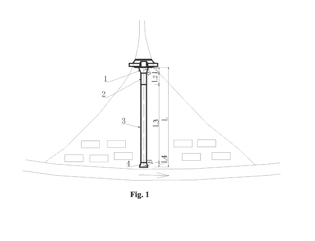
[0026]As shown in FIG. 1, the debris flow gully contains a viscous debris flow, the drainage area is 5.4 km2, and the length of the accumulation fan is 260 m. To control debris flow disasters, a prevention and control scheme based on constructing a check dam group in the drainage basin and constructing a drainage channel on the accumulation fan is planned. The drainage channel is divided into a big-end-up bell-mouthed inlet section 1, an acceleration section 2, a main channel section 3 in which the debris flow flows in a balanced mode, and a big-end-down bell-mouthed outlet section 4 along the flow direction of the debris flow; the drainage channel is constructed of concrete materials. Therefore, the limited flow velocity of the drainage channel is determined to be 8.0 m / s. A method for planning and designing the above drainage channel comprises the following steps.

[0027](1) According to the topographic condition of the debris flow accumulation fan, plan the drainage channel at the ...

embodiment 2

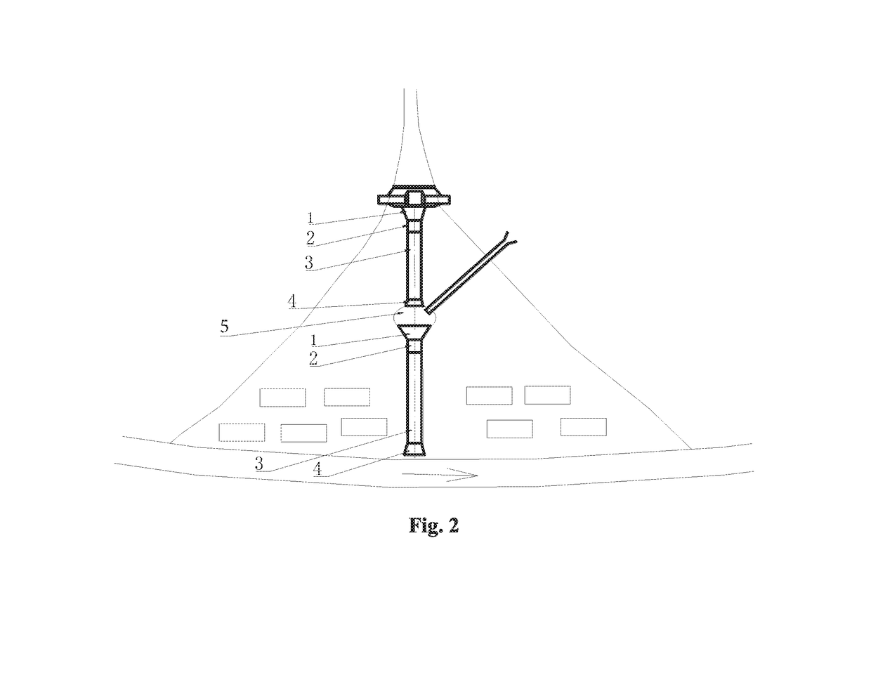
[0032]As shown in FIG. 1 and FIG. 2, the flow in the debris flow gully is a dilute debris flow, the drainage area is 8.6 km2, and the length of the accumulation fan is 500 m. To control debris flow disasters, a prevention and control scheme based on constructing a check dam group in the drainage basin and a drainage channel on the deposited fan is planned. Because the length of the debris flow-deposited fan is greater than 300 m, the proposed drainage channel includes two relatively independent debris flow drainage channels (i.e., an upper drainage channel and a lower drainage channel), which are connected in an end-to-end mode from upstream to downstream. Transition zone 5 is arranged between the upper and lower drainage channels, its along-the-flow direction of the debris flow is 20 m, and it is used to accommodate the afflux of the debris flow in a tributary ditch on the surface of the fan.

[0033]The upper drainage channel is divided into a big-end-up bell-mouthed inlet section 1,...

embodiment 3

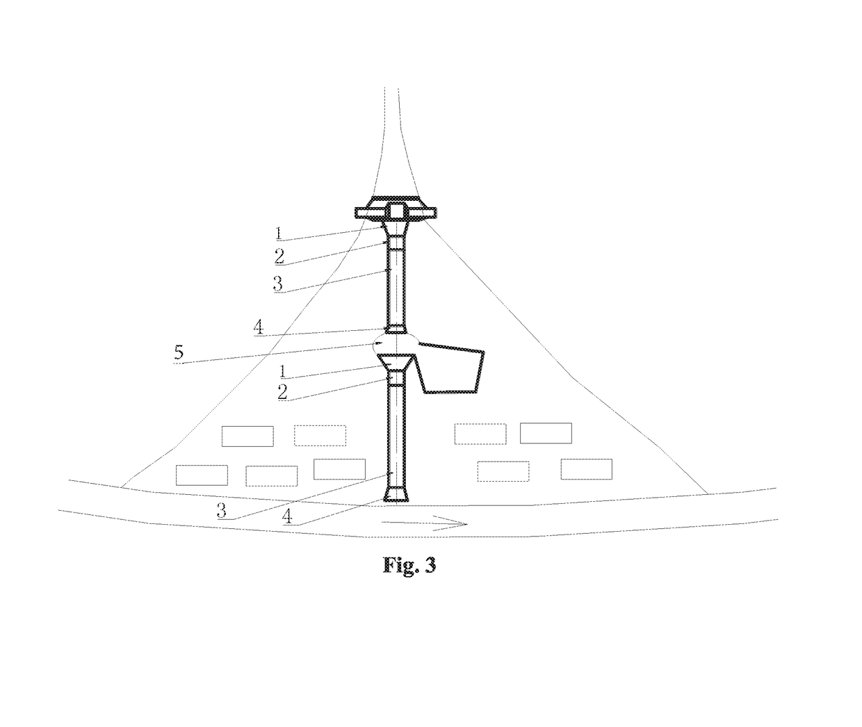
[0045]As shown inFIG. 1 and FIG. 3, the details identical to embodiment 2 are not repeated. Embodiments 3 and 2 differ as follows: transition zone 5 is used to lead out part of a debris flow to stop depositing, and a filed for stopping depositing is provided at the left side of the transition zone that faces the lower drainage channel.


PUM


Abstract

A method for planning and designing a debris flow drainage channel is provided. The position and total length of the drainage channel and a longitudinal slope of a gully bed of the drainage channel are determined. An inlet section, an outlet section and an acceleration section of the drainage channel are formed as fully lined channel type. After determining the length of the inlet section and the included angle between the side wall of the inlet section and the main channel, the length of the outlet section and the included angle between the side wall of the outlet section and the main channel, and the length of the acceleration section, the channel type and the length of the main channel section are also determined.

Description

FIELD OF THE INVENTION[0001]The invention relates to debris flow control technology, particularly to a method for planning and designing debris flow drainage channels and applications thereof for both debris flow accumulation fans with a length below 300 meters and debris flow accumulation fans with a length over 300 meters.BACKGROUND OF THE INVENTION[0002]The density of a debris flow is far higher than the density of a water flow, and the fluidic dualistic structure of the debris flow, which contains clastic soil, has particularity and shows the characteristics of high inertia, strong transport force, and huge impact force. Due to the severe erosion produced by debris flow movement, a gully bed undergoes severe changes that can cause bottom tearing of the gully bed and the collapse of a gully bank, adding solid matter sources that replenish the debris flow, thereby increasing the damage it causes. Drainage channels are among the main engineering measures for the prevention and cont...

Claims


Application Information

Patent Timeline
Patent Type & Authority Patents(United States)
IPC IPC(8): E02B1/02E02B3/02E02B5/00E02B3/10
CPCE02B1/02E02B3/02E02B5/00Y02A10/383E02B3/10Y02A10/30
Inventor CHEN, XIAOQINGYOU, YONGCUI, PENGCHEN, JIANGANGZOU, YUHUAWANG, TAO
Owner INST OF MOUNTAIN HAZARDS & ENVIRONMENT CHINESE ACADEMY OF SCI
Why Eureka
Try Eureka