Method for planning and designing debris flow drainage channels and applications thereof
a technology of debris flow and drainage channel, applied in stream regulation, hydraulic models, instruments, etc., can solve the problems of increasing damage, increasing the flow velocity of debris flow at the upper increasing the flow velocity of debris flow at the lower end of the main channel, so as to maintain the safe operation of the drainage channel, prevent severe erosion, and efficiently drain the debris flow downstream
- Summary
- Abstract
- Description
- Claims
- Application Information
AI Technical Summary
Benefits of technology
Problems solved by technology
Method used
Image
Examples
embodiment 1
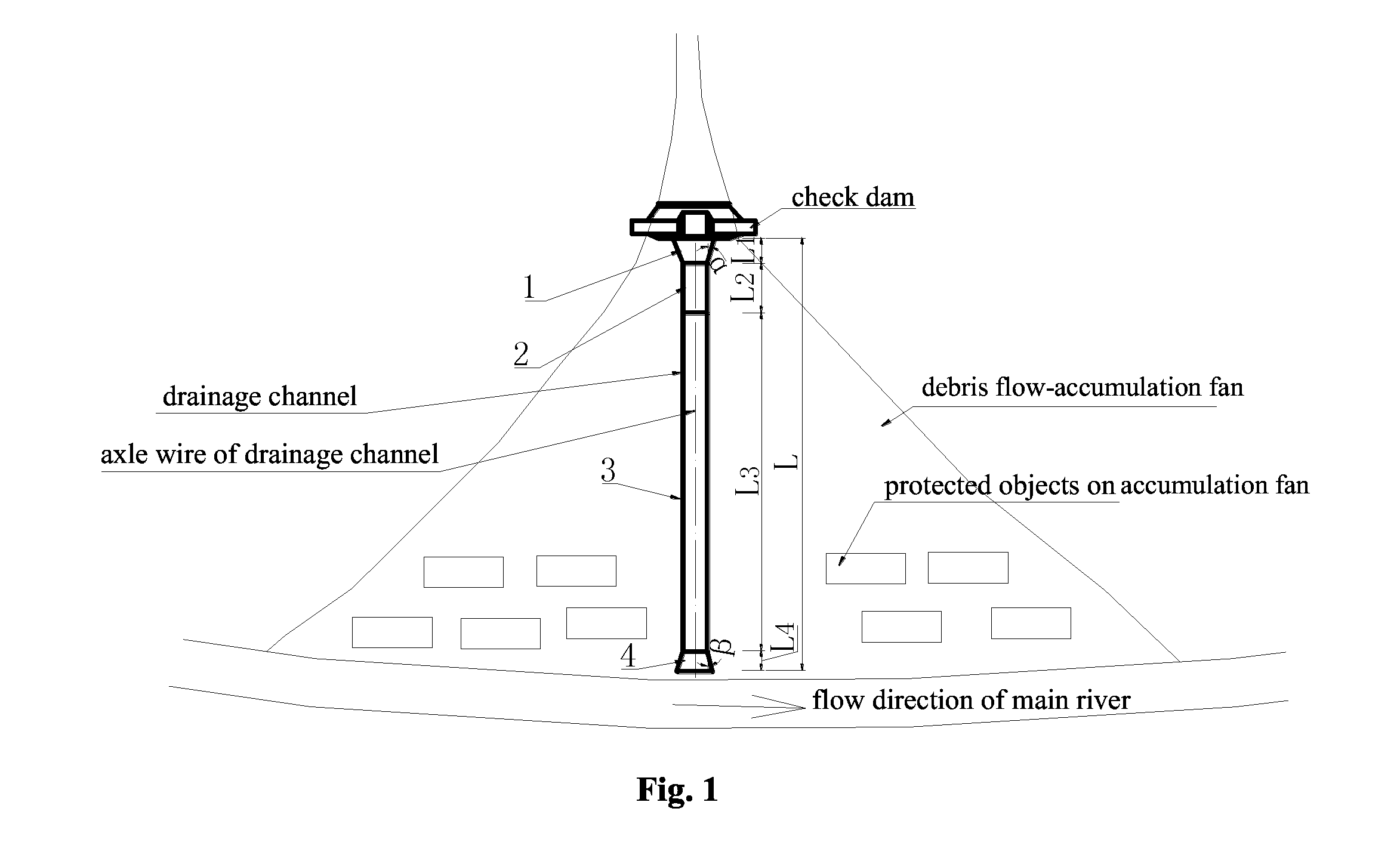
[0023]As shown in FIG. 1, the debris flow gully contains a viscous debris flow, the drainage area is 5.4 km2, and the length of the accumulation fan is 260 m. To control debris flow disasters, a prevention and control scheme based on constructing a check dam group in the drainage basin and constructing a drainage channel on the accumulation fan is planned. The drainage channel is divided into a big-end-up bell-mouthed inlet section 1, an acceleration section 2, a main channel section 3 in which the debris flow flows in a balanced mode, and a big-end-down bell-mouthed outlet section 4 along the flow direction of the debris flow; the drainage channel is constructed of concrete materials. Therefore, the limited flow velocity of the drainage channel is determined to be 8.0 m / s. A method for planning and designing the above drainage channel comprises the following steps.
[0024](1) According to the topographic condition of the debris flow accumulation fan, plan the drainage channel at the ...
embodiment 2
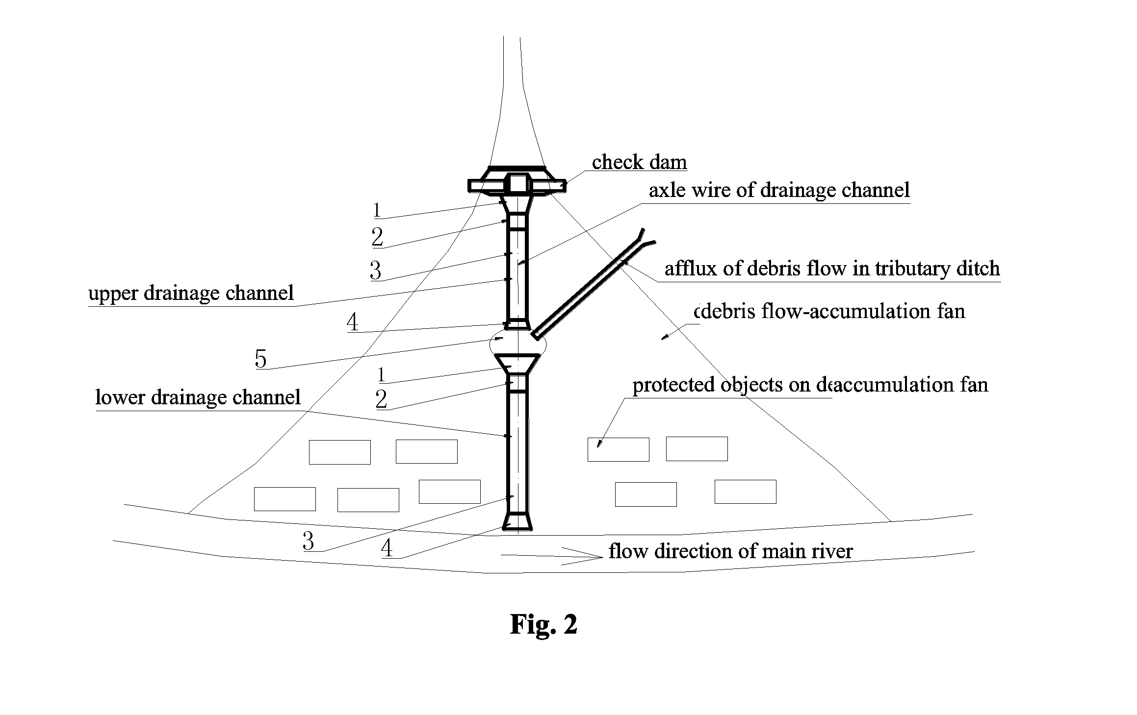
[0029]As shown in FIG. 1 and FIG. 2, the flow in the debris flow gully is a dilute debris flow, the drainage area is 8.6 km2, and the length of the accumulation fan is 500 m. To control debris flow disasters, a prevention and control scheme based on constructing a check dam group in the drainage basin and a drainage channel on the deposited fan is planned. Because the length of the debris flow-deposited fan is greater than 300 m, the proposed drainage channel includes two relatively independent debris flow drainage channels (i.e., an upper drainage channel and a lower drainage channel), which are connected in an end-to-end mode from upstream to downstream. Transition zone 5 is arranged between the upper and lower drainage channels, its along-the-flow direction of the debris flow is 20 m, and it is used to accommodate the afflux of the debris flow in a tributary ditch on the surface of the fan.
[0030]The upper drainage channel is divided into a big-end-up bell-mouthed inlet section 1,...
embodiment 3
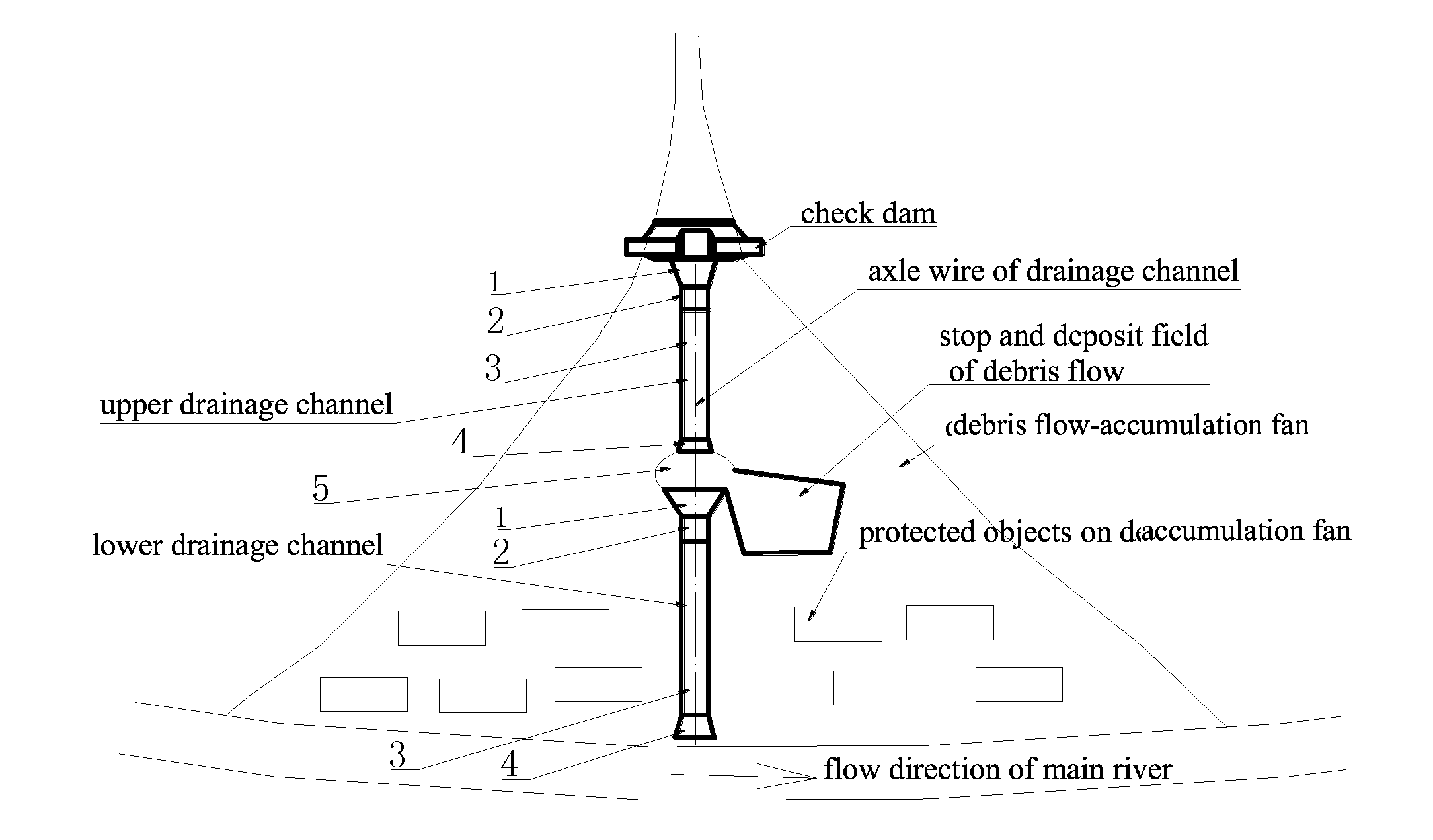
[0042]As shown in FIG. 1 and FIG. 3, the details identical to embodiment 2 are not repeated. Embodiments 3 and 2 differ as follows: transition zone 5 is used to lead out part of a debris flow to stop depositing, and a filed for stopping depositing is provided at the left side of the transition zone that faces the lower drainage channel.
PUM
 Abstract
Description
Claims
Application Information
 - R&D
- Intellectual Property
- Life Sciences
- Materials
- Tech Scout
- Unparalleled Data Quality
- Higher Quality Content
- 60% Fewer Hallucinations
Browse by: Latest US Patents, China's latest patents, Technical Efficacy Thesaurus, Application Domain, Technology Topic, Popular Technical Reports.
© 2025 PatSnap. All rights reserved.Legal|Privacy policy|Modern Slavery Act Transparency Statement|Sitemap|About US| Contact US: help@patsnap.com


