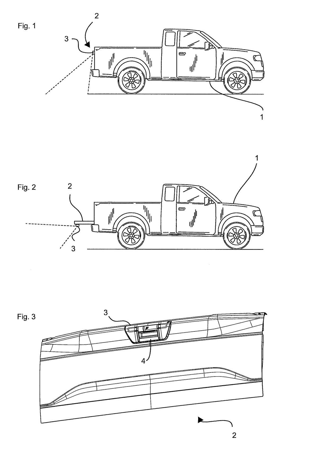
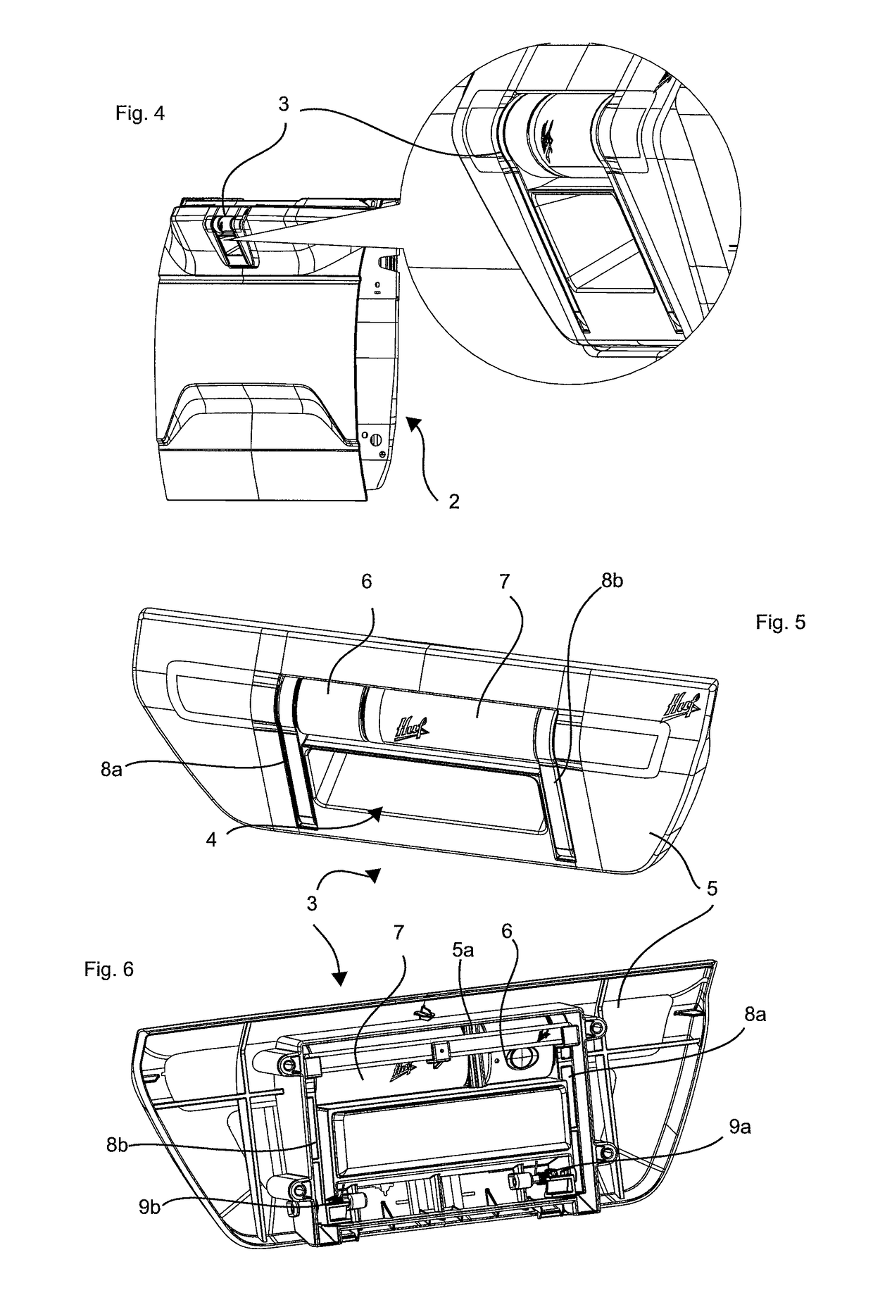
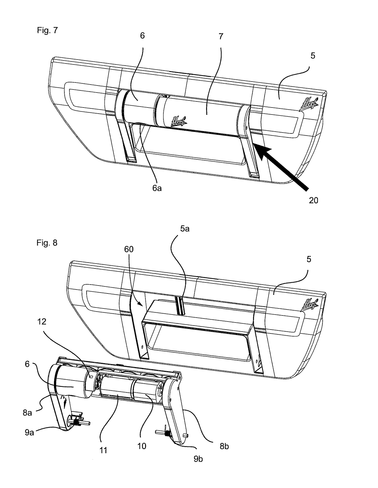
Rear view camera system for a motor vehicle
a camera system and rear view technology, applied in closed circuit television systems, vehicle components, instruments, etc., can solve the problems of increasing the variability of recording the surrounding area, and the danger of damage to the camera optical system
- Summary
- Abstract
- Description
- Claims
- Application Information
AI Technical Summary
Benefits of technology
Problems solved by technology
Method used
Image
Examples
first embodiment
[0134]FIGS. 11 to 15 show an impact protection 70a, which is designed in the form of an elastic pressure spring. In this connection, the bar-like support element 50a is supported at the elastic pressure spring 51, wherein it also serves as an attachment for the eccentric component 12. Under compression of the elastic pressure spring 51, the bar or support element 50 can be shifted in relation to the carrier assembly 5 or into the recess 60. For this purpose, the support element 50a is incorporated in a guide 52 in which it is retained in movable fashion by means of a pressure spring 50a. The guide 52 of the support element 50a is shown in FIG. 12. When a force is exerted on the camera optical system 6 (or on the drive unit 7 of the camera optical system 6, which also protrudes from the carrier assembly), the camera optical system 6 can be pushed back into the carrier assembly 5 by power transmission of the eccentric component 12 against the compression force, i.e., the evasive force...
second embodiment
[0136]The first and second embodiment of the impact protection 70a, 70b, can be described in an abstract manner in such a way that the respective support element 50a, 50b is elastically coupled with the carrier assembly 5, so that the support element 50a, 50b can be moved and / or elastically deformed in relation to the carrier assembly 5 by overcoming the evasive force of the impact protection 70a, 70b.
[0137]FIGS. 19 to 21 show a third embodiment of the impact protection 70c. In contrast to the first and second embodiment, here the support element 5a is again designed in the form of a rigid bar, which is fixed at the carrier assembly 5. In the third embodiment, the eccentric component 12 represents the impact protection 70c. This impact protection 70c is characterized in that the eccentric component 12 has at least one outer peripheral region 12a that is designed in elastically deformable manner. The importance of this elastically deformable outer peripheral region 12a is subsequent...
third embodiment
[0138]FIGS. 22 to 24 show by means of a third embodiment a modification of the impact protection 70c. In this modification, the impact protection 70c has a two-part design and comprises a spring element 110 consisting of metal and a housing 200 of the camera optical system 6. At the same time, the spring element 110 is mounted at the housing 200 of the camera optical system 6 and forms the eccentric component 12, which is supported at the support element 5a when it is rotated about the adjustable axis 33. As a result, the camera optical system 6 assumes the position shown in FIG. 23, in which the camera optical system 6 protrudes from the recess 60 of the carrier assembly 5. The function of the impact protection shown 70c in FIGS. 22 to 24 corresponds to the operating modes of the embodiments shown in FIGS. 19 to 21, so that reference can be made to these embodiments. Even in the embodiment shown in FIG. 24, the spring element 110, which has an elastically deformable and semicircula...
PUM
 Abstract
Description
Claims
Application Information
 - R&D
- Intellectual Property
- Life Sciences
- Materials
- Tech Scout
- Unparalleled Data Quality
- Higher Quality Content
- 60% Fewer Hallucinations
Browse by: Latest US Patents, China's latest patents, Technical Efficacy Thesaurus, Application Domain, Technology Topic, Popular Technical Reports.
© 2025 PatSnap. All rights reserved.Legal|Privacy policy|Modern Slavery Act Transparency Statement|Sitemap|About US| Contact US: help@patsnap.com


