Method of installing a fixture

a technology of installing a fixture and a fixture body, which is applied in the direction of additive manufacturing processes, machine supports, manufacturing tools, etc., can solve the problems of fixture positioning, fixture bores, and fastener operation, so as to facilitate fastener and/or automated procedures

Active Publication Date: 2019-02-26
AIRBUS OPERATIONS GMBH
View PDF13 Cites 71 Cited by
  • Summary
  • Abstract
  • Description
  • Claims
  • Application Information

AI Technical Summary

Benefits of technology

[0004]It is therefore one idea of the present invention to provide a new and improved method or technique for overcoming one or more of the problems discussed above. In particular, it would be useful to provide a new method of installing a fixture or bracket in a fuselage structure of an aircraft or spacecraft, with which a faster and / or an automated procedure may be facilitated.
[0010]In this way, the installation of the fixture may essentially occur automatically with the formation of the fixture itself. Thus, the method provides maximum flexibility in the fuselage assembly procedure and does not require separate or external manufacture of individual fixtures or brackets. There is also no need for any inventory of spare parts, as the fixtures are created directly from the digital model during installation. Similarly, there is no need for non-flying parts, e.g. which may be required to fix a bracket on the structure during a curing process but which are then later removed. Accordingly, the design of the fixtures can encompass a full range of variants and can be adapted or modified readily as the design parameters change.
[0015]The positioning and movement of the additive manufacturing apparatus may be computer-controlled. For example, the additive manufacturing apparatus or the head thereof may be provided on a robotic assembly or a robotic arm, which is controllable to move and position the head of the apparatus based upon the 3D digital model of the fixture. In this way, a very precise positioning of a fixture or bracket in or on the body structure can be achieved, and with a high level of repeatability.

Problems solved by technology

Some disadvantages of mechanical fasteners, like rivets and screws, include that the fixture or bracket requires bores for the fasteners, that the fixture needs to be positioned with respect to the bores, and that it requires a fastening operation to then secure the fasteners.
These steps naturally involve process costs.
Some disadvantages of adhesive attachment include that both the fixture or bracket and the attachment surface may require pre-treatment, such as roughening and / or degreasing, and that an adhesive application operation is needed, then followed by operations to position and mount the fixture or bracket under application of pressure.
These steps again involve process costs.

Method used


Image

  • Method of installing a fixture
  • Method of installing a fixture
  • Method of installing a fixture

Examples


Embodiment Construction

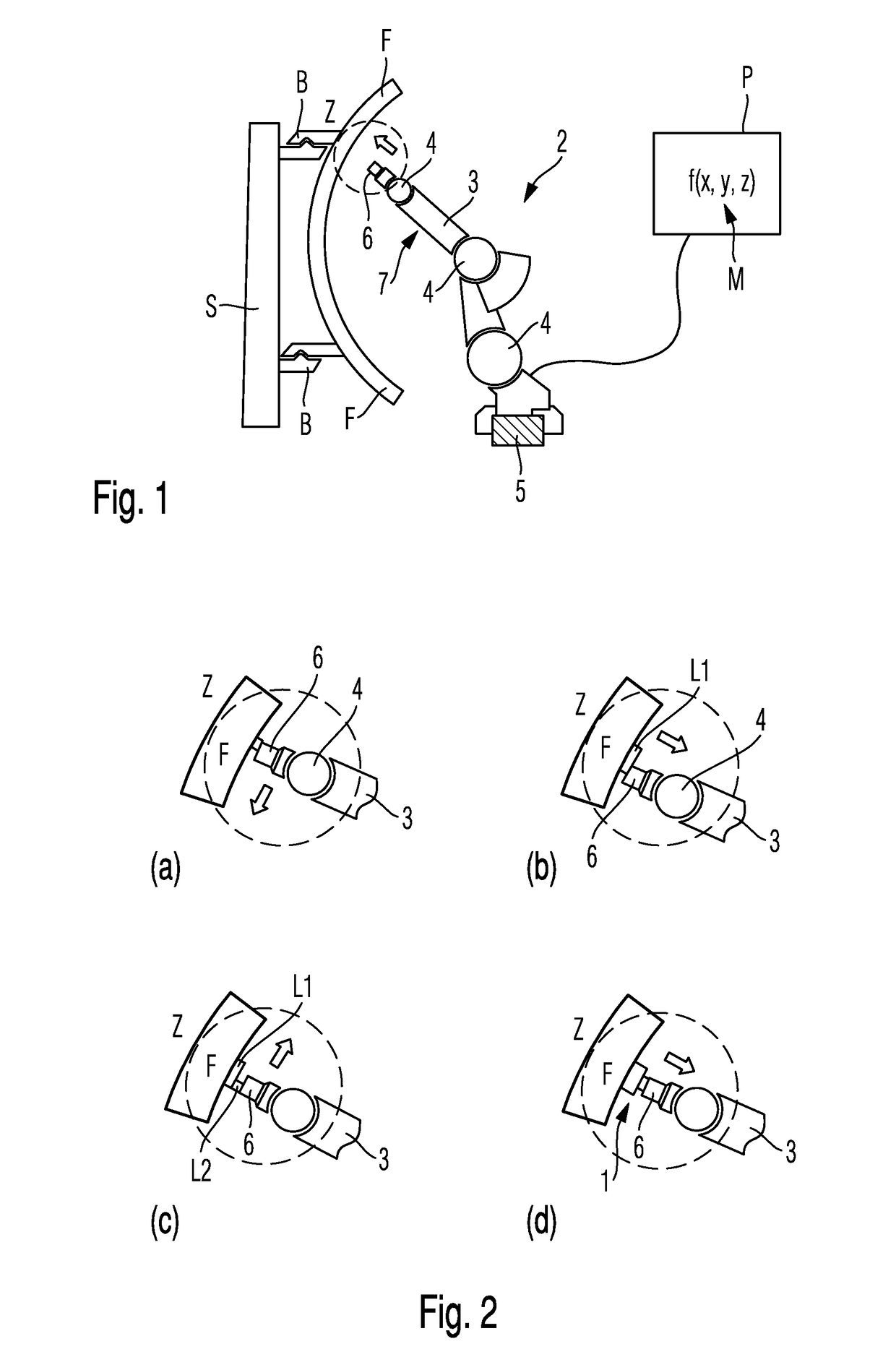
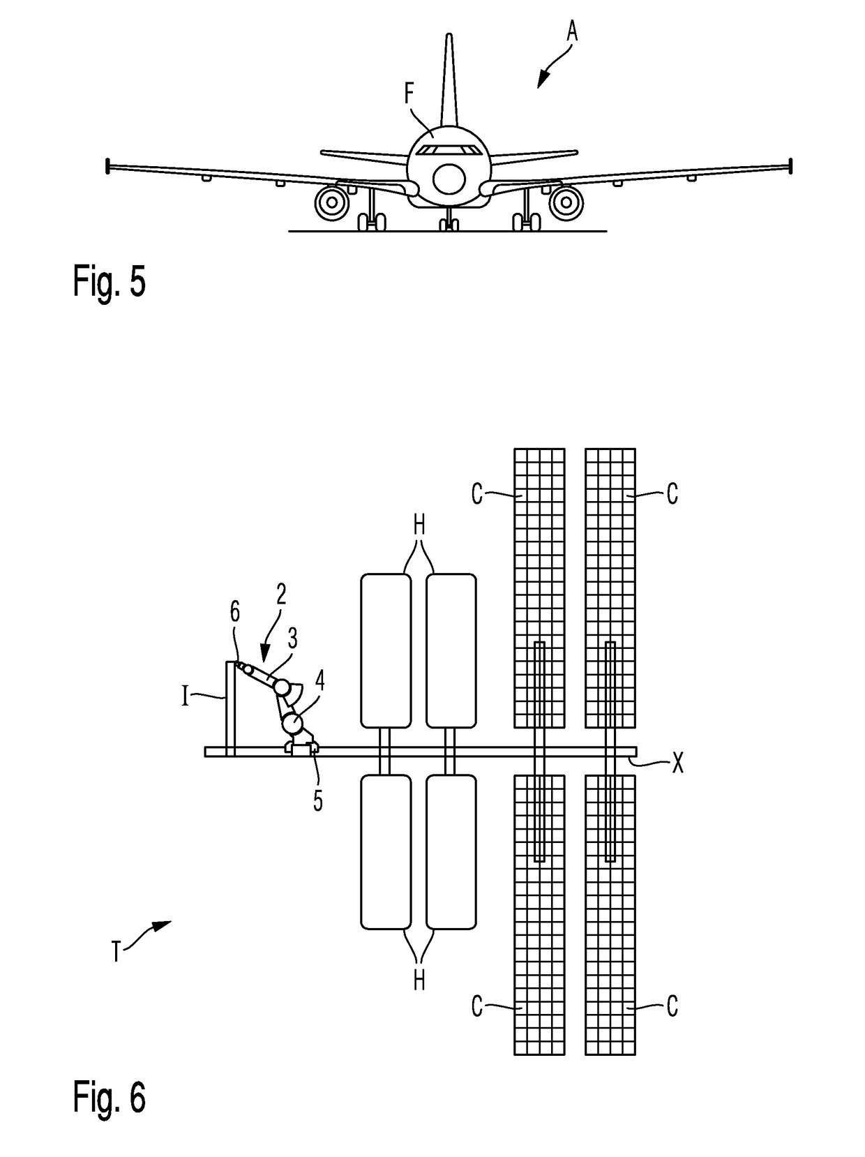
[0037]With reference firstly to FIG. 1 of the drawings, a system for installing a fixture 1 (here in the form of a bracket) in an airframe or fuselage structure F of an aircraft according to a method of the invention is illustrated schematically. The airframe or fuselage structure F of the aircraft in this embodiment comprises a curved shell section of the fuselage, comprised of a carbon-fibre reinforced polymer composite, which is supported in this case by brace elements B extending horizontally from a vertically extending supporting framework S. Also shown in FIG. 1 is a robot assembly 2, which includes a robotic arm 3 having a plurality of articulated joints 4, each of which is drivable in at least one and preferably in a number of degrees-of-freedom. The robot assembly 2 is itself mounted for translational movement along a rail member 5 in a direction perpendicular to a plane of drawing FIG. 1.

[0038]Mounted on a distal end region of the robot arm 3 is a head 6 of an additive man...


PUM

PropertyMeasurementUnit
densityaaaaaaaaaa
pressureaaaaaaaaaa
flexibilityaaaaaaaaaa

Abstract

A method of installing a fixture, such as a bracket, in a fuselage structure of an aircraft includes the steps of: providing or generating a three-dimensional digital model of the fixture; arranging a head of an additive manufacturing apparatus in the fuselage structure; and forming the fixture in situ in the fuselage structure with the head of the additive manufacturing apparatus based upon the digital model of the fixture. The fixture is installed in the fuselage structure by bonding or fusing the fixture to the fuselage structure as the fixture is formed. A fixture, such as a bracket, which is generated in situ in a fuselage structure of an aircraft based upon a three-dimensional digital model, wherein the fixture is bonded or fused to the fuselage structure as the fixture is formed.

Description

TECHNICAL FIELD[0001]The present invention relates to a method of installing a fixture, such as a bracket, on a body structure of a vehicle, particularly a body or fuselage structure of an aircraft or spacecraft, for mounting or attaching items or systems with respect to that structure. The invention also relates to a fixture, such as a bracket, installed in or on a vehicle, especially an aircraft or spacecraft, and thus to the vehicle itself incorporating such a fixture. It will be noted that the term “spacecraft” as used herein includes satellites and space-station modules, as well as rocket modules or parts.BACKGROUND OF THE INVENTION[0002]The installation of items and / or systems, such as electrical systems with conduits and cables, in nautical, aeronautical or automotive applications typically involves the use of mounting fixtures or brackets which need to be secured to a structure (e.g. a vehicle chassis or hull structure) for then supporting those systems. Conventionally, thes...

Claims


Application Information

Patent Timeline
Patent Type & Authority Patents(United States)
IPC IPC(8): B29C67/00F16M13/02B64F5/10B29C64/106B64C1/00B22F5/00B22F7/06
CPCB64C1/00B22F5/00F16M13/02B29C64/106B64F5/10B22F7/062B29C64/118
Inventor GOEHLICH, ROBERT ALEXANDER
Owner AIRBUS OPERATIONS GMBH
Why Eureka
Try Eureka