Systems and methods to increase rigidity and snag-resistance of catheter tip

a technology of rigidity and snag resistance, which is applied in the direction of catheters, metal working devices, metal-working devices, etc., can solve the problems of high pressure within the infusion system, failure of the infusion system components, and undesirable acceleration of infused fluid, so as to achieve faster and more efficient rapid infusion procedures

Active Publication Date: 2016-08-02
BECTON DICKINSON & CO
View PDF89 Cites 27 Cited by
  • Summary
  • Abstract
  • Description
  • Claims
  • Application Information

AI Technical Summary

Benefits of technology

[0012]The systems and methods of the present disclosure have been developed in response to problems and needs in the art that have not yet been fully resolved by currently available infusion systems and methods. Thus, these systems and methods are developed to provide for safer and more efficient rapid infusion procedures.
[0014]In some embodiments, a tip portion of the intravenous catheter is modified to include a plurality of diffusion holes. The tip portion generally comprises a tapered profile, wherein the outer and inner surface of the tip taper towards the distal end of the catheter. The tapered outer surface provides a smooth transition between the narrow diameter of the catheter tip opening and the larger diameter of the catheter tubing. Thus, as the tip of the catheter is introduced into the vein of a patient, the tapered outer surface facilitates easy insertion of the catheter through the access hole. The tapered inner surface is generally provided to tightly contact the outer surface of an introducer needle housed within the lumen of the catheter. The introducer needle is provided to create an opening into the vein of patient through which the catheter tip is inserted. The tapered inner surface ensures a tight seal between the inner surface of the catheter and the outer surface of the needle. Following placement of the catheter, the introducer needle is removed.
[0015]In some implementations, a peripheral catheter is provided comprising a catheter body having an outer surface, a proximal end, a distal end, a lumen extending between the proximal and distal ends, and a distal lumen opening, the catheter further including a recess formed in the outer surface of the catheter body. In some implementations, a diffusion hole is further positioned within the recess through a wall thickness of the catheter body. As such, the recessed location of the diffusion hole is removed from directly contacting the skin or other tissues of the patient during insertion of the catheter. Accordingly, the diffusion hole is prevented from snagging the skin or tissues of the patient.
[0016]In some implementations, a method for manufacturing a snag-resistant, vented catheter is provided, wherein the method includes the steps of providing a catheter body having an outer surface, a proximal end, a distal end, a lumen extending between the proximal and distal ends, and a lumen opening. The method further includes the steps of providing a recess in the outer surface of the catheter body, and further providing a diffusion hole in the recess through a wall thickness of the catheter body. As such, the recessed location of the diffusion hole is removed from directly contacting the skin or other tissues of the patient during insertion of the catheter. Accordingly, the diffusion hole is prevented from snagging the skin or tissues of the patient.
[0017]Further, in some implementations, a peripheral catheter is provided comprising a catheter body having a predetermined wall thickness, the catheter body member having a proximal end, a distal end, a lumen extending between the proximal and distal ends, and a distal lumen opening, the catheter body further having a truncated length to access a peripheral vein of a patient. In some implementations, the peripheral catheter further comprises a recess formed in the outer surface of the catheter body, wherein a hole is provided within the recess through the predetermined wall thickness and in communication with the lumen. As such, the recessed location of the diffusion hole is removed from directly contacting the skin or other tissues of the patient during insertion of the catheter. Accordingly, the diffusion hole is prevented from snagging the skin or tissues of the patient.

Problems solved by technology

Power injection procedures generate high pressures within the infusion system, thereby requiring specialized vascular access devices, extension sets, media transfer sets, pump syringes, and bulk or pre-filled contrast media syringes.
Power injections of viscous media at this injection rate produce significant back pressure within the infusion system that commonly results in a failure of the infusion system components.
This acceleration of the infused fluid is undesirable for several reasons.
For example, the tapered catheter results in a greater backpressure for the remainder of the catheter assembly.
This effect is undesirable due to the limitations of the pumping capacity of the infusion pump as well as the limited structural integrity of the components and subcomponents of the infusion system.
For example, if the backpressure becomes too great, the pump's efficiency may decrease and certain seals or connections within the infusion system may fail.
Additionally, the fluid acceleration in the catheter tip results in a recoil force that may cause the catheter tip to shift within the patient's vein thereby displacing the catheter and / or damaging the patient's vein and / or injection site.
In some procedures, the fluid jet may pierce the patient's vein wall thereby leading to extravasation or infiltration.
Not only is this uncomfortable and painful to the patient, but infiltration may also prevent the patient from receiving the needed therapy.
However, addition of diffuser holes at or near the tip of a catheter also reduces the buckling resistance of the catheter thereby making the catheter tip more susceptible to crushing during insertion.
As a result, the addition of diffuser holes may result in failed catheterization and physical pain to the patient.
This too may result in failed catheterization, physical pain and / or physical damage to the patient.
Thus, while methods and systems currently exist to reduce exit velocity of an infusant during rapid infusion procedures, challenges still exist.

Method used


Image

  • Systems and methods to increase rigidity and snag-resistance of catheter tip
  • Systems and methods to increase rigidity and snag-resistance of catheter tip
  • Systems and methods to increase rigidity and snag-resistance of catheter tip

Examples


Embodiment Construction

[0029]Embodiments of the present invention will be best understood by reference to the drawings, wherein like reference numbers indicate identical or functionally similar elements. It will be readily understood that the components of the present invention, as generally described and illustrated in the figures herein, could be arranged and designed in a wide variety of different configurations. Thus, the following more detailed description, as represented in the figures, is not intended to limit the scope of the invention as claimed, but is merely representative of presently preferred embodiments of the invention.

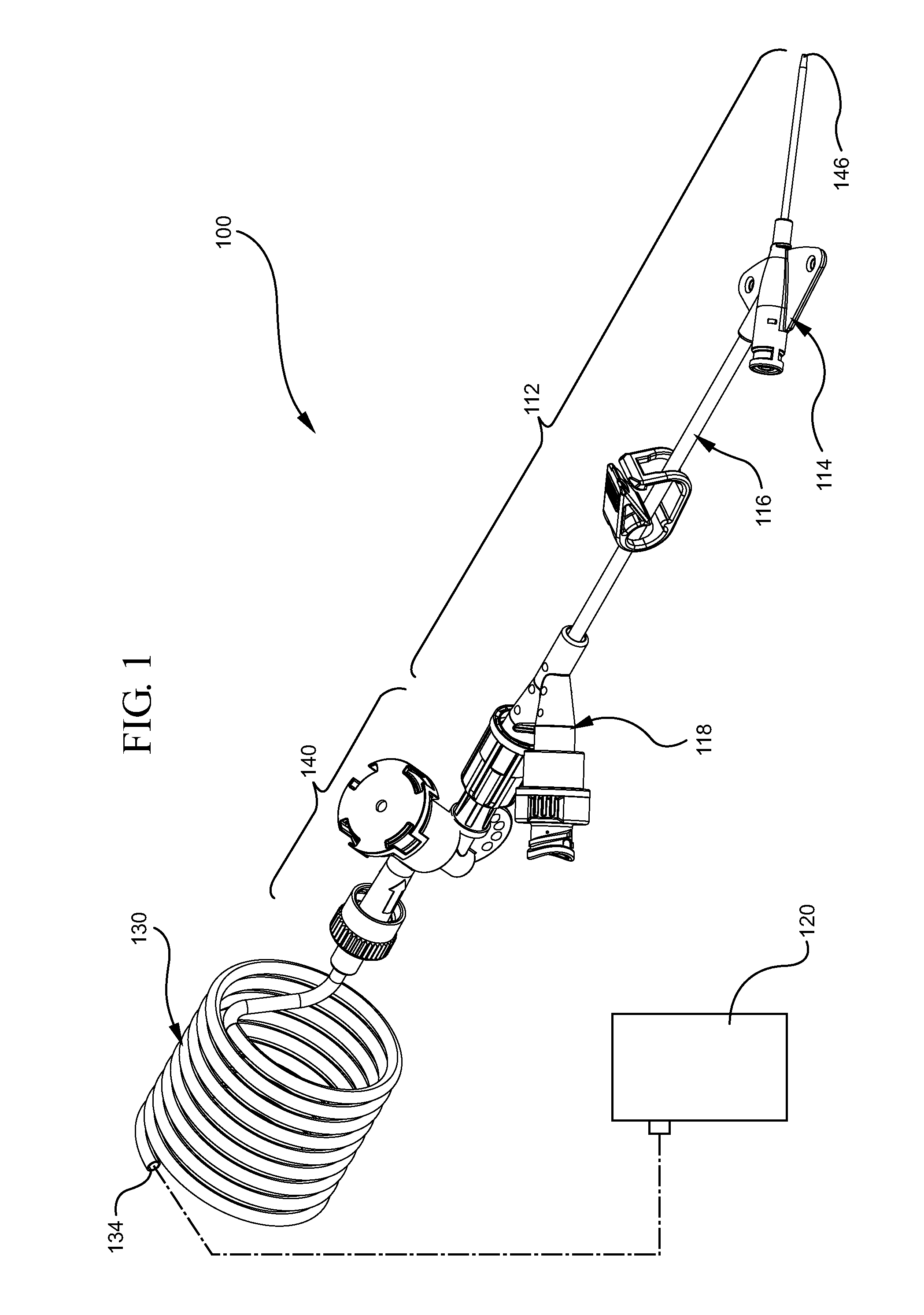
[0030]The systems and methods of the present invention are generally designed for use in combination with a vascular infusion system capable of rapidly delivering an infusant to the vascular system of a patient. Referring now to FIG. 1, a vascular infusion system 100 is shown, in accordance with a representative embodiment of the present invention. Infusion systems of this t...


PUM

PropertyMeasurementUnit
internal pressuresaaaaaaaaaa
angleaaaaaaaaaa
angleaaaaaaaaaa

Abstract

A venous catheter having a catheter tip comprising recessed diffusion holes for increasing the snag-resistance of the venous catheter. The invention further provides systems and methods for providing axial ridges interposed between diffusion holes for increasing the rigidity of the vented catheter tip.

Description

BACKGROUND OF THE INVENTION[0001]The present invention relates generally to vascular infusion systems and components, including catheter assemblies and devices used with catheter assemblies. In particular, the present invention relates to systems and methods for increasing the rigidity and snag-resistance of a catheter tip of a vascular infusion system having catheter hole arrays to provide enhanced infusion flow rates, lower system pressures, and reduced catheter exit jet velocities. Additionally, the present invention relates to improving the overall rigidity of a thin-walled structure.[0002]Vascular access devices are used for communicating fluid with the anatomy of a patient. For example, vascular access devices, such as catheters, are commonly used for infusing fluid, such as saline solution, various medicaments, and / or total parenteral nutrition, into a patient, withdrawing blood from a patient, and / or monitoring various parameters of the patient's vascular system.[0003]A vari...

Claims


Application Information

Patent Timeline
Patent Type & Authority Patents(United States)
IPC IPC(8): A61M25/00
CPCA61M25/0015A61M25/007A61M25/0068A61M25/008A61M2025/0073Y10T29/49826
Inventor SHEVGOOR, SIDDARTH K.
Owner BECTON DICKINSON & CO
Why Eureka
Try Eureka