Pseudo random sequences in array lidar systems

a technology of array lidar and random sequences, applied in the field of pseudo random sequences in array lidar systems, can solve problems such as difficult resolution of reflections at the receiver

Active Publication Date: 2019-02-26
GM GLOBAL TECH OPERATIONS LLC
View PDF1 Cites 40 Cited by
  • Summary
  • Abstract
  • Description
  • Claims
  • Application Information

AI Technical Summary

Problems solved by technology

While the illuminators of an array lidar may be used in turn, simultaneous transmission by the array may result in reflections that are not easily resolved at the receiver.

Method used


Image

  • Pseudo random sequences in array lidar systems
  • Pseudo random sequences in array lidar systems
  • Pseudo random sequences in array lidar systems

Examples


Embodiment Construction

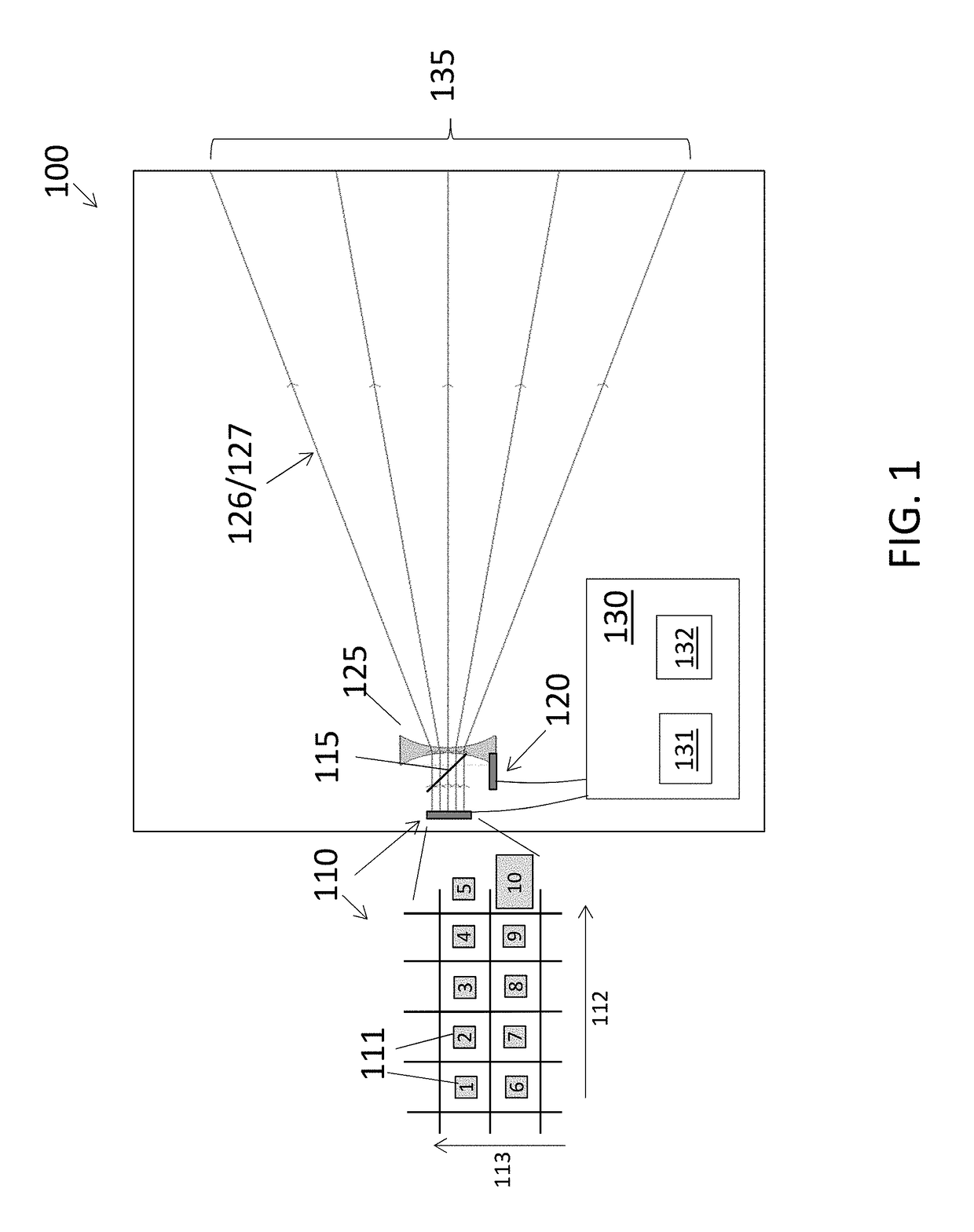
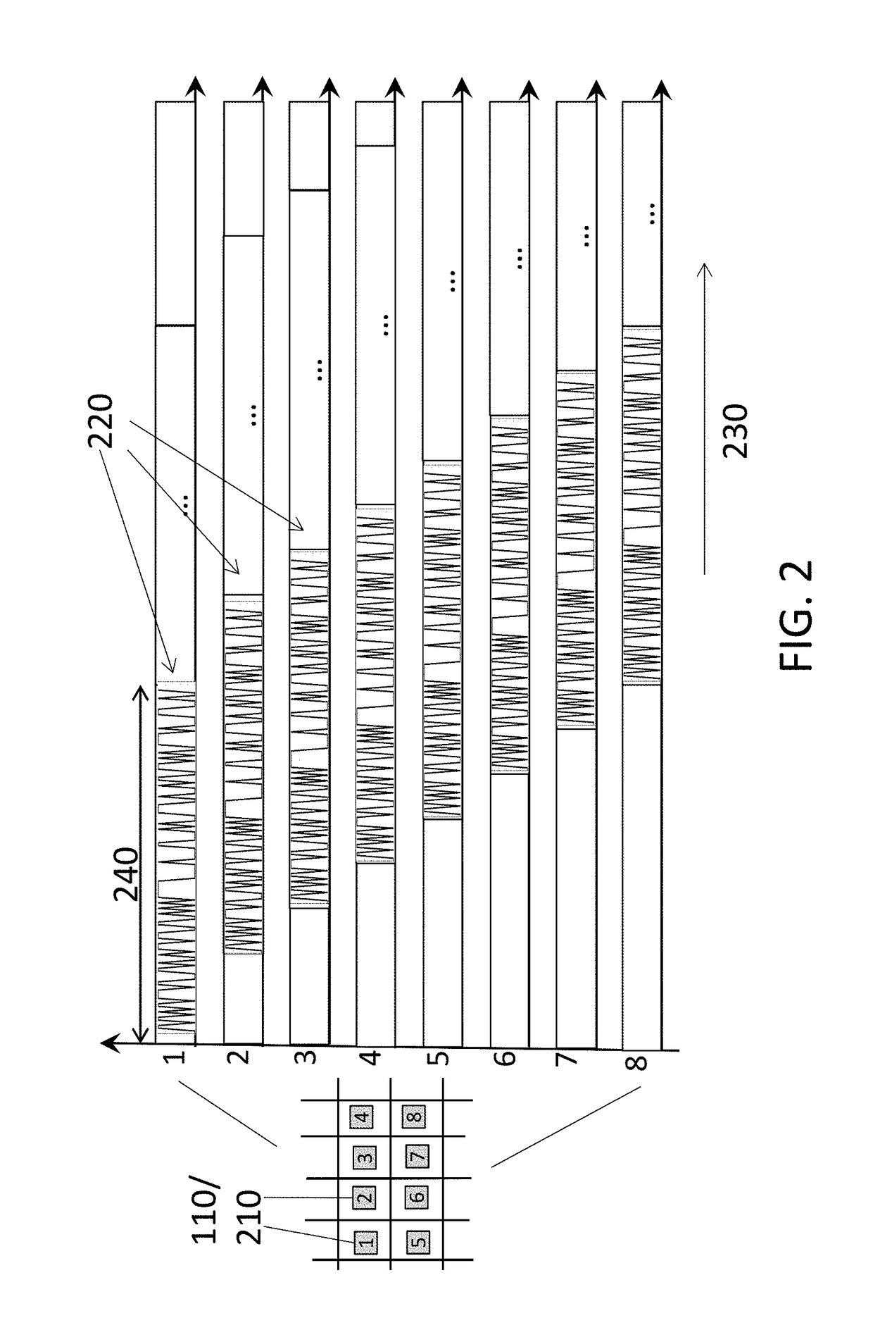
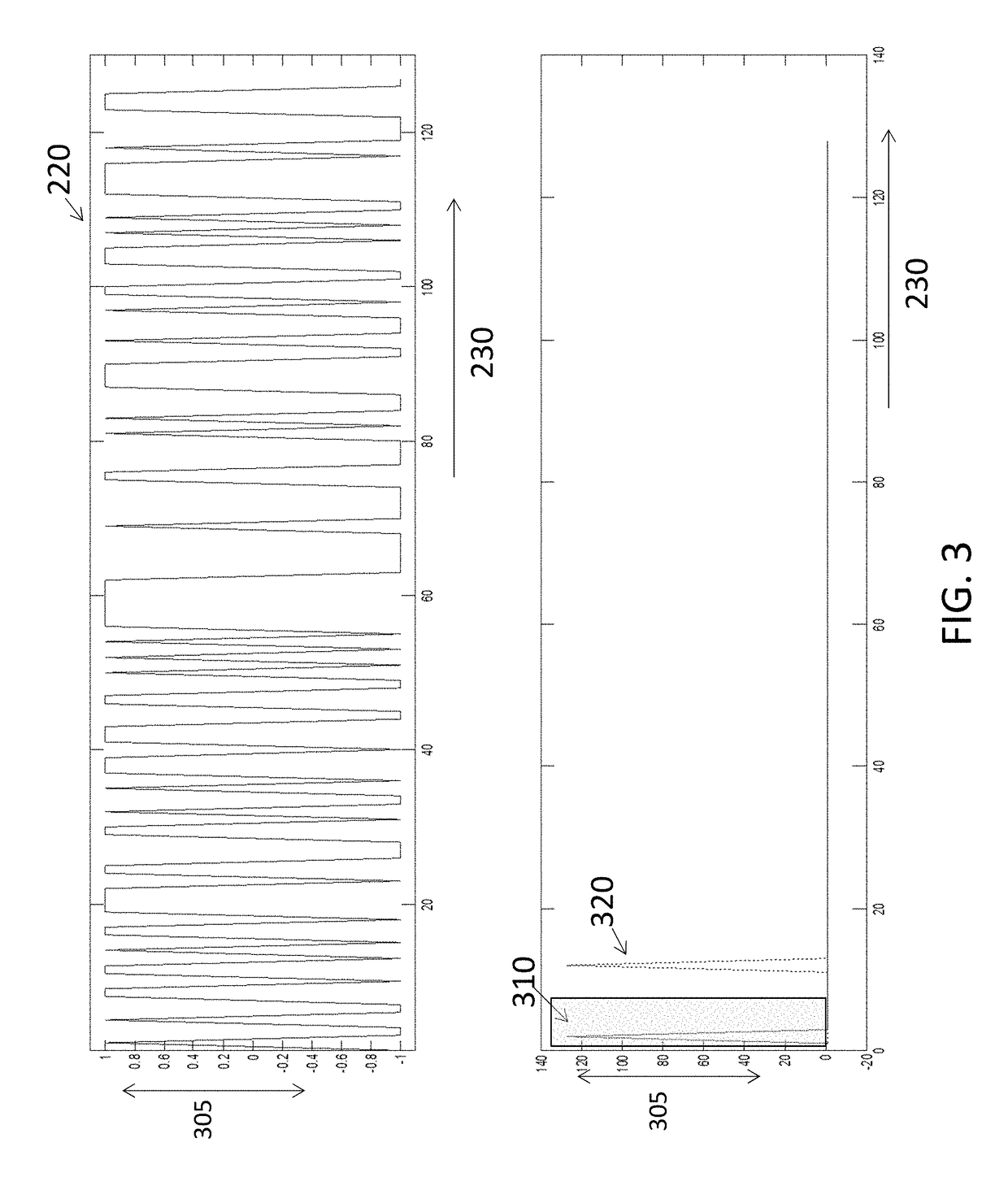
[0012]As noted above, lidar systems are used for detection and ranging. Lidar systems have diverse applications in areas such as landslide investigations, archaeology, oil and gas exploration, meteorology, and navigation (e.g., obstacle detection) in automotive applications. As also noted, concurrently transmitting light from multiple illuminators of an array results in multiple reflections that must be resolved to remove ambiguity and obtain meaningful information. Prior array lidar systems have avoided the interference among reflections by transmitting from each illuminators of the array in turn in a time division multiple access (TDMA) scheme. Embodiments of the systems and methods discussed herein relate to concurrent transmission, with two or more illuminators of the array lidar, of pulse sequences that facilitate resolution or differentiation of the reflections associated with each illuminator on the receiver side. Specifically, the transmission from each illuminator is of a s...


PUM


Abstract

A method of performing ranging and detection with an array lidar system and the array lidar system include a first illuminator to transmit a first pseudorandom binary sequence of pulses, the first pseudorandom sequence of pulses resulting in first reflections, and a second illuminator to transmit a second pseudorandom sequence of pulses, the second pseudorandom sequence of pulses being transmitted at least partly concurrently with transmission of the first pseudorandom sequence of pulses, the second pseudorandom sequence of pulses resulting in second reflections. A receiver receives the first reflections and the second reflections and associates the first reflections with the first illuminator based on a result of correlating the first reflections with the first pseudorandom sequence of pulses and a result of correlating the first reflections with the second pseudorandom sequence of pulses, the receiver includes an optical detector array and a processor.

Description

CROSS-REFERENCE TO RELATED APPLICATION[0001]This application is a Non-Provisional of U.S. Provisional Application No. 62 / 158,281 filed May 7, 2015, the disclosure of which is incorporated herein by reference in its entirety.FIELD OF THE INVENTION[0002]The subject invention relates to pseudo random sequences in array lidar systems.BACKGROUND[0003]Lidar, which may be referred to as light radar or laser array light detection and ranging, refers generally to transmitting light at an object and receiving and processing a resulting reflection. An array of illuminators may be used in a lidar system to obtain reflections from a wider field of view than is possible with a single illuminator. While the illuminators of an array lidar may be used in turn, simultaneous transmission by the array may result in reflections that are not easily resolved at the receiver. Accordingly, it is desirable to provide an array lidar system that facilitates concurrent transmission and simplified processing of ...

Claims


Application Information

Patent Timeline
Patent Type & Authority Patents(United States)
IPC IPC(8): G01S7/48G01S17/42G01S7/481G01S7/486G01S17/10G01S7/484G01S17/89G01S7/4865G01S17/26
CPCG01S7/484G01S7/4815G01S7/4816G01S17/89G01S17/102G01S17/42G01S7/4865G01S7/483G01S17/26
Inventor SCHEIM, KOBI J.LIPSON, ARIELGAZIT, RAN Y.BIALER, ODED
Owner GM GLOBAL TECH OPERATIONS LLC
Why Eureka
Try Eureka