
Method of eliminating power converter input power variations and minimizing energy storage capacitor requirements for a pulsed load system

a pulsed load system and power converter technology, applied in the field of power system and power conversion, can solve problems such as power disturbance, damage to generator vibration, and disturbance of other equipment, and achieve the effects of reducing the requirement of energy storage capacitors, reducing the requirement of power converter input power variations, and reducing the requirement of power converter input power

Active Publication Date: 2019-02-26
RAYTHEON CO
View PDF14 Cites 1 Cited by
  • Summary
  • Abstract
  • Description
  • Claims
  • Application Information

AI Technical Summary

Benefits of technology

The patent provides a method to reduce power converter input power variations and minimize energy storage capacitor requirements for a pulsed load system. The technical effect is to improve the stability and efficiency of the system.

Problems solved by technology

Drawing pulsed power from a utility or a generator causes voltage disturbances which can disturb other equipment on the same power distribution bus.
The pulsed load can also cause damaging vibrations in the generator and heating of the windings due to the higher rms current of the pulsed input power.
The slow loop acts as a low pass filter such that the converter supplies a constant current to the capacitor bank, which attenuates the pulsed load current and therefore has practical limitations in the maximum attenuation.

Method used


Image

  • Method of eliminating power converter input power variations and minimizing energy storage capacitor requirements for a pulsed load system
  • Method of eliminating power converter input power variations and minimizing energy storage capacitor requirements for a pulsed load system
  • Method of eliminating power converter input power variations and minimizing energy storage capacitor requirements for a pulsed load system

Examples


Embodiment Construction

[0018]It should be understood at the outset that, although example embodiments are illustrated below, the present invention may be implemented using any number of techniques, whether currently known or not. The present invention should in no way be limited to the example implementations, drawings, and techniques illustrated below. Additionally, the drawings are not necessarily drawn to scale.

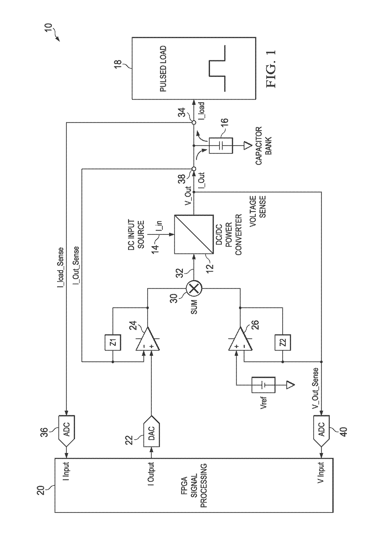
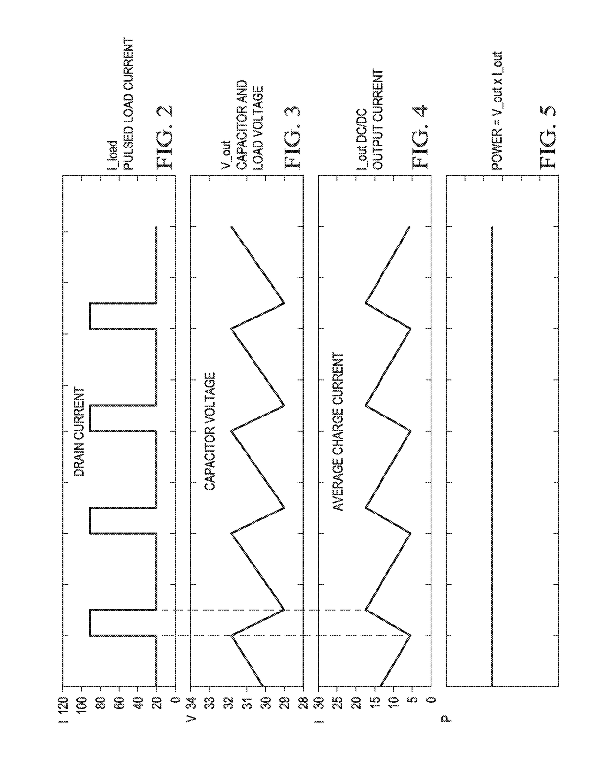
[0019]This disclosure includes a controller that dynamically calculates the power converter output current required to achieve constant power at the power converter input. This disclosure includes an algorithm that calculates and generates the ideal converter output current waveform required to achieve a perfectly constant input power, even with large voltage variations on the capacitor bank. The capacitor bank voltage droop during the transmit period is (Ipeak−Icharge)×Pulsewidth / Capacitance. This disclosure raises the charge current to the capacitor bank as the capacitor bank voltage droops re...


PUM


Abstract

A power system having a controller coupled to a power converter and configured to sense a pulsed load current and a load voltage, and configured to control the power converter such that the power converter draws a constant power from a power source to avoid disturbances in the power source while delivering the pulsed load current. The controller is configured to determine an average value of the pulsed load current and an average value of the load voltage to determine an average power delivered to the load. The controller is configured to dynamically establish the charge current to a capacitor bank as a function of the sensed instantaneous load voltage such that the power converter draws a constant power from the power source.

Description

TECHNICAL FIELD[0001]The present disclosure is directed in general to power systems and power conversion, and more specifically to power systems providing a large pulsed current to a load.BACKGROUND OF THE DISCLOSURE[0002]Power systems with pulsed loads e.g. large radars typically have a large pulsed load during a radar transmit period, followed by a smaller load during a radar receive period. If the power system has limited energy storage, the system input power profile will follow the pulsed load. Drawing pulsed power from a utility or a generator causes voltage disturbances which can disturb other equipment on the same power distribution bus. The pulsed load can also cause damaging vibrations in the generator and heating of the windings due to the higher rms current of the pulsed input power.[0003]The traditional solution for a pulsed power system is to have a large capacitor bank which provides the peak power to the load during the pulse, and the capacitor bank energy is repleni...

Claims


Application Information

Patent Timeline
IPC IPC(8): H02M3/04
CPCH02M3/04H02M1/15H02M11/00
Inventor MCGINTY, JOHNREID, STEPHEN R.CUERDEN, ALAN
Owner RAYTHEON CO
Learn More