

Method for the production of electrodes and electrodes made using such a method
a production method and electrode technology, applied in the field of electrodes, can solve the problems of reducing the achievable energy density, affecting the production efficiency of electrodes, and affecting the production efficiency of electrodes, and achieve the effect of low electrode porosity
- Summary
- Abstract
- Description
- Claims
- Application Information
AI Technical Summary
Benefits of technology
Problems solved by technology
Method used
Image

Examples
example 1
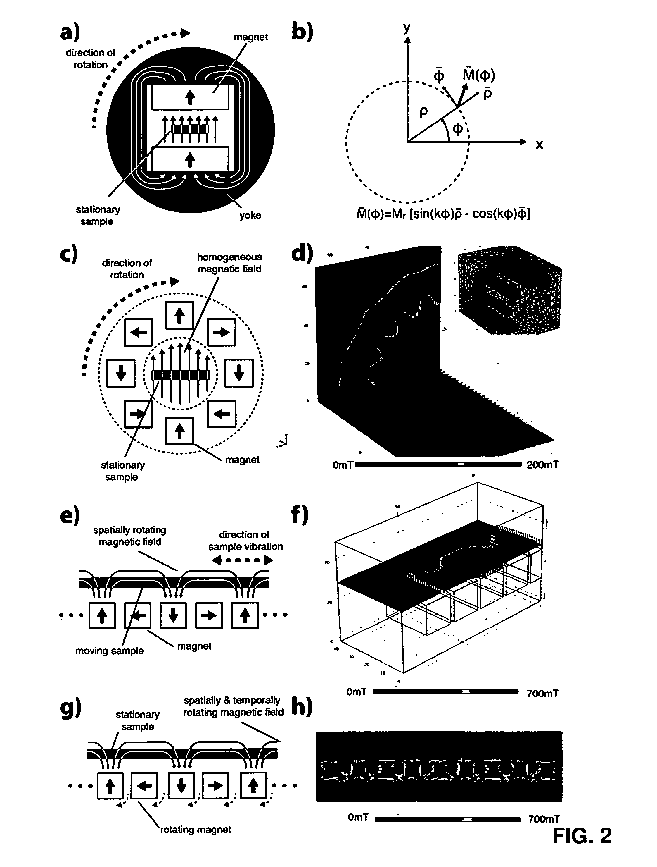
Method for Making a Slurry with Non-Spherical Electrically Conducting Microparticles with Nanoparticles Deposited on their Surface and Using Such a Slurry for the Making of an Electrode Using a Halbach Cylinder
Making of the Slurry:
[0104]5 g graphite particles (d90=32 μm, aspect ratio >6) were dispersed in 40 ml deionized H2O. 200 μl cationic ferrofluid (EMG605, FerroTec GmbH, Germany) were added to the suspension and stirred for 30 min. Ultrasonic agitation was applied for 10 min. The suspension was washed 3 times with the following procedure: a. Suspension was placed in a centrifuge at 9000 rpm for 5 min; b. Supernatant was decanted, 40 ml deionized H2O added; c. Precipitate was dispersed by stirring; Suspension was placed in a centrifuge at 9000 rpm for 5 min, supernatant decanted. Precipitate was dried at 120° C. for 24 h.
Electrode Slurry Preparation:
[0105]2.7 g nanoparticle decorated graphite was mixed with 3 g polymeric binder suspension (10 wt % PVDF in NMP) and 2 g solvent (N...
example 2
Method for Making a Slurry with Non-Spherical Electrically Conducting Microparticles with Nanoparticles Deposited on their Surface and Using Such a Slurry for the Making of an Electrode Using a Halbach Cylinder
Synthesis of Concentrated, TMAH Stabilized Ferrofluid:
[0107]5.6 g iron(II) chloride tetrahydrate FeCl2*4 H2O was dissolved in 14 ml 2 M HCl to create a Fe2+ precursor. 3.02 g iron(III) chloride hexahydrate FeCl3*6 H2O was dissolved in 11.2 ml 2 M HCl to create a Fe3+ precursor. 1 ml of Fe2+ precursor and 4 ml Fe3+ precursor were mixed in a glass container. 1M NH4OH was added drop wise over 5 min while stirring. A permanent magnet was placed below the glass container and the supernatant was decanted after the magnetic nanoparticles accumulated near the magnet, 30 ml deionized H2O was added and the supernatant decanted again. The magnet was removed, 30 ml deionized H2O added and stirred. The magnet was placed below the glass container and the supernatant not completely decanted....
example 3
Synthesis of Diluted, pH Stabilized Ferrofluid
[0111]5.6 g iron(II) chloride tetrahydrate FeCl2*4 H2O was dissolved in 14 ml 2 M HCl to create a Fe2+ precursor. 3.02 g iron(III) chloride hexahydrate FeCl3*6 H2O was dissolved in 11.2 ml 2 M HCl to create a Fe3+ precursor. 1 ml of Fe2+ precursor and 4 ml Fe3+ precursor were mixed in a glass container. 1M NH4OH were added drop wise over 5 min while stirring. A permanent magnet was placed below the glass container and the supernatant was decanted after the magnetic nanoparticles accumulated near the magnet. The magnet was removed, 30 ml deionized H2O added and stirred. pH value was adjusted to 10 by drop wise addition of diluted NH4OH and HCl to stabilize suspension.
Nanoparticle Deposition and Electrode Fabrication:
[0112]2.7 g graphite particles (d90=32 μm, aspect ratio >6) were mixed with 2.3 ml deionized H2O and 700 μl nanoparticle suspension in a high shear mixer for 5 min. 130 mg NaCl was added, suspension is high shear mixed for 10 ...
PUM
| Property | Measurement | Unit |
|---|---|---|
| Fraction | aaaaa | aaaaa |
| Fraction | aaaaa | aaaaa |
| Diameter | aaaaa | aaaaa |
Abstract
Description
Claims
Application Information