Electrical energy storage module and method for producing an electrical energy storage module

a technology of energy storage module and energy storage module, which is applied in the direction of cell components, final product manufacturing, sustainable manufacturing/processing, etc., can solve the problems of eddy current and loss in current-carrying regions, and achieve the effect of reducing the total inductance of the energy storage module, reducing the loss of electrical contact resistance, and reducing the loss of nonreactive losses

Active Publication Date: 2015-10-22
ROBERT BOSCH GMBH
View PDF3 Cites 8 Cited by
  • Summary
  • Abstract
  • Description
  • Claims
  • Application Information

AI Technical Summary

Benefits of technology

[0028]In the case of the present invention, it is considered to be particularly advantageous that a return line is effected via the cell housing of the energy storage cells, as a result of which separate return conductors are largely dispensed with. Owing to the fact that large contact surfaces are realized via the cell housing, an electrical contact resistance is small, as a result of which nonreactive losses can be kept low. An area enclosed between forward and return conductor and hence a resulting total inductance of the energy storage module can advantageously be minimized. In addition, space for further components (for example gas collector) can be provided in this way. Owing to the flat design of the cell connection elements and the return conductor, the energy storage module can be designed to be very low and hence space-saving.
[0029]Another considerable advantage of such an arrangement is considered to be that power loss, in particular when high-frequency alternating current is drawn from the energy storage module, can be significantly reduced. In particular, in the case of battery systems with integrated inverter, so-called battery direct inverters (BDI), in which a rapid change in the current direction through a battery module leads to variation of the voltage, said reduction in the power loss is very advantageous. The energy storage modules are advantageous with respect to the drawing of direct current, too, since they have reduced nonreactive losses owing to very low-resistance contact being made.
[0030]Moreover, by the avoidance of inductive loss components with the energy storage cells, an electromagnetic compatibility (EMC) can be improved since emitted electromagnetic fields can be reduced and disturbing influences on adjacent electronic components can be reduced as a result. Furthermore, nonreactive losses, for example owing to the skin effect, are meaningfully reduced, which advantageously effects an increased degree of efficiency and lower heat generation of the energy storage module.

Problems solved by technology

In addition, at operating frequencies in the kHz range, losses can occur in the current-carrying regions and eddy currents can occur in electrically conductive surfaces, for example in the housing, owing to the skin effect.

Method used


Image

  • Electrical energy storage module and method for producing an electrical energy storage module
  • Electrical energy storage module and method for producing an electrical energy storage module
  • Electrical energy storage module and method for producing an electrical energy storage module

Examples


Embodiment Construction

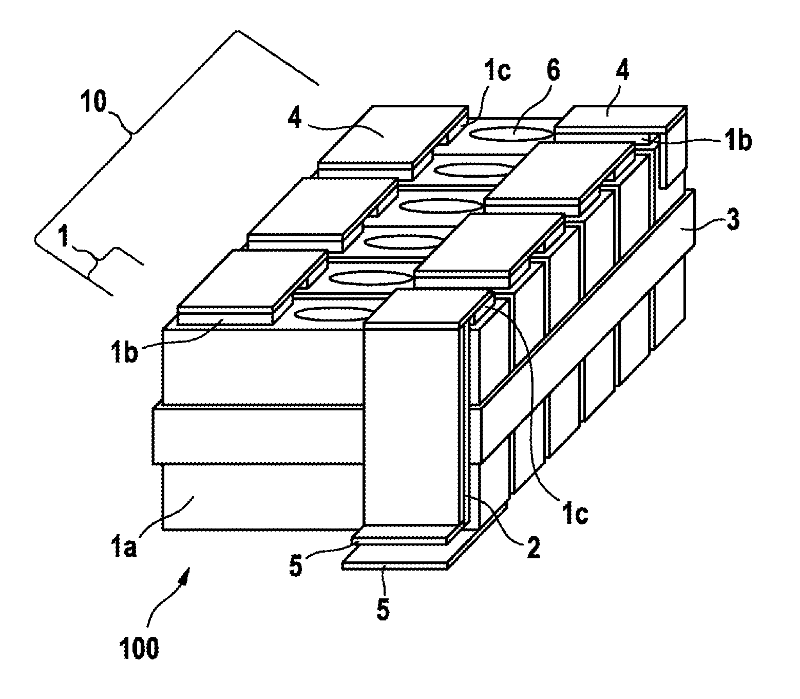
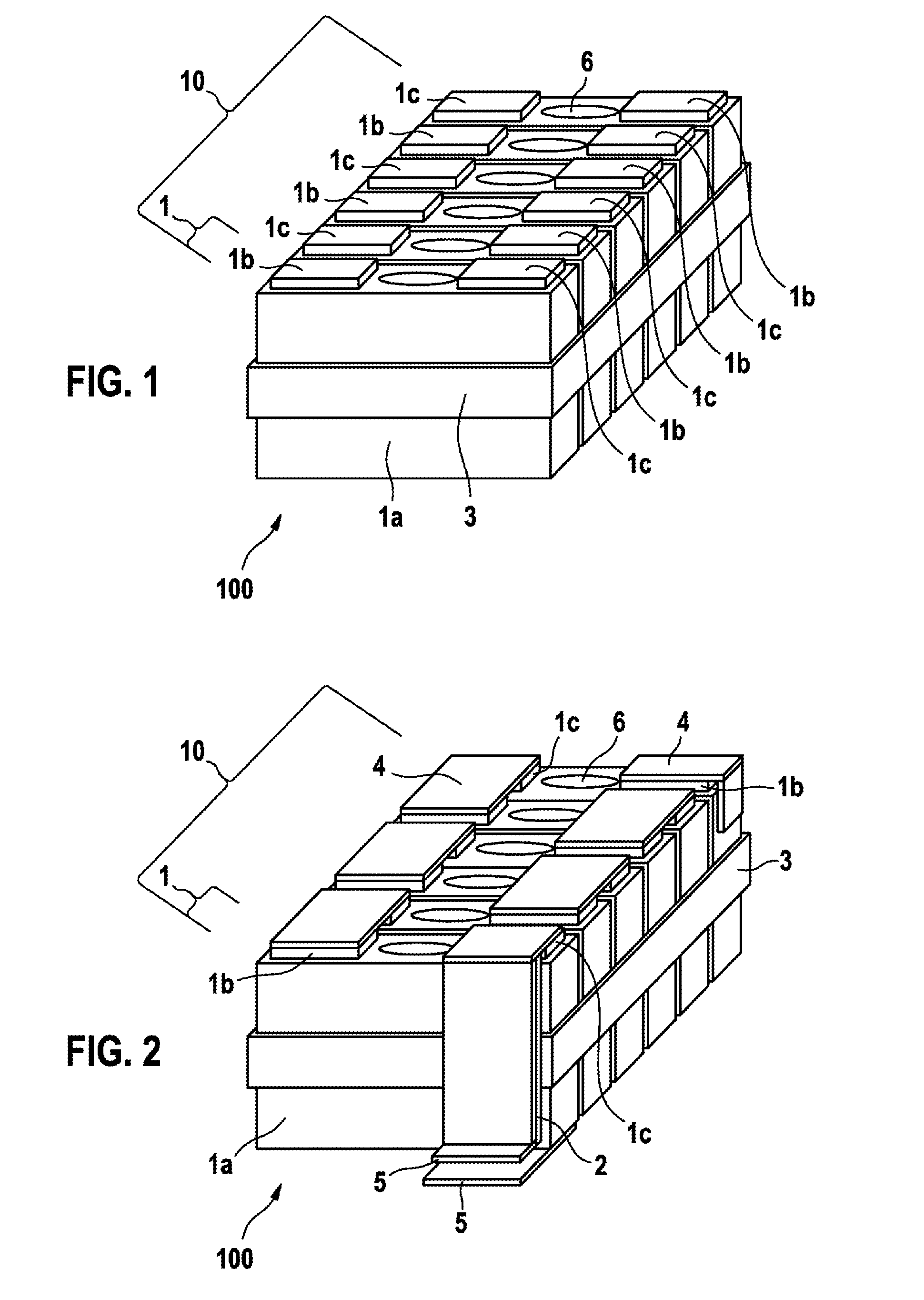
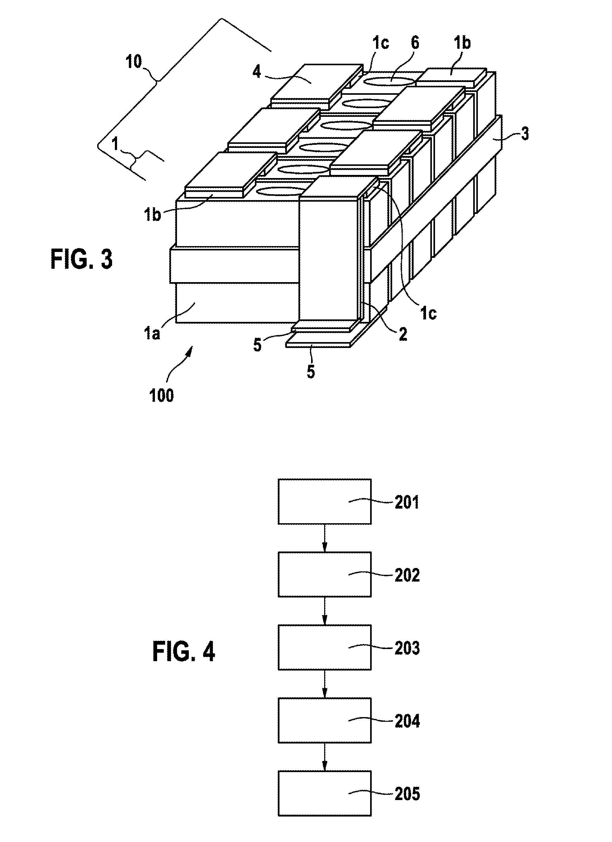
[0037]The direction terminology used below, that is to say terms such as “on the left”, “on the right”, “at the top”, “at the bottom”, “in front”, “behind”, “above the latter”, “behind the latter”, “first”, “last” and the like, is used merely for the purpose of better understanding of the drawings and should not be considered in any case to constitute a limitation of the generality.

[0038]Electrical energy storage cells according to the present invention comprise all devices which can store electrical energy over a predefined time period and can output it again over a further time period. Energy storage cells, according to the present invention comprise here all types of secondary and primary energy stores, in particular electrically capacitive, electrochemical (Faraday's) and store types which operate in a combined fashion.

[0039]The time periods which are considered can comprise here from seconds up to hours, days or years. Electrical energy storage cells can comprise, for example, ...


PUM

PropertyMeasurementUnit
drive frequenciesaaaaaaaaaa
polaritiesaaaaaaaaaa
resistanceaaaaaaaaaa

Abstract

The invention provides an electrical energy storage module (100), comprising: at least one storage cell stack (10), comprising: a plurality of energy storage cells (1), which each have a cell housing (1a) each having two pole connections (1b,1c), wherein the energy storage cells (1) are arranged in series in the storage cell stack (10) in such a way that in each case a first pole connection (1b) and a second pole connection (1c) having different polarities of two adjacent energy storage cells (1) are galvanically connected to one another by means of flat cell connecting elements (4), wherein the cell housings (1a) of all of the energy storage cells (1) are galvanically connected to one another, wherein the first pole connection (1b) of an energy storage cell (1) arranged at a first end of the storage cell stack (10) is galvanically connected to the cell housing (1a), and wherein the second pole connection (1c) of an energy storage cell (1) arranged at a second end of the storage cell stack (10) and the cell housings (1a) each have a flat return conductor (5).

Description

BACKGROUND OF THE INVENTION[0001]The invention relates to an electrical energy storage module and a method for producing an electrical energy storage module.[0002]Usually, direct current is drawn from electrical energy storage cells or direct current is fed into same. Therefore, the previously known design of energy storage cells is configured for the optimization of the nonreactive internal resistances and the specific energy or power density of the energy storage cells.[0003]In many applications of electrical energy storage cells, storage cells are mutually interconnected in series or in parallel arrangement to form battery modules in order to set desired output parameters such as total electric voltage, electric voltage range, energy content or power density, for example. If currents with increasing AC component are drawn from such energy storage cells, an influence of distributed inductance of the energy storage cells increases as a function of frequency. In addition, at operati...

Claims


Application Information

Patent Timeline
Patent Type & Authority Applications(United States)
IPC IPC(8): H01M2/20H01M10/052H01M10/04H01M2/10H01M50/124H01M50/209H01M50/264H01M50/503H01M50/51H01M50/55H01M50/553H01M50/566
CPCH01M2/202H01M2/204H01M2/206H01M10/04H01M2/1022H01M2/1077H01M10/052H01M2/1016H01G11/12H01G11/76H01M10/0481H01M50/124H01M50/1245H01M50/553H01M50/51H01M50/55H01M50/503H01M50/566H01M50/209H01M50/264Y02E60/10Y02P70/50Y02E60/13
Inventor TIEFENBACH, ANDYPROEPPER, THOMASKESSLER, MARTIN
Owner ROBERT BOSCH GMBH
Why Eureka
Try Eureka