Fuel cell
a fuel cell and cell technology, applied in the field of fuel cells, can solve the problems of difficult to maintain the temperature of the cooling gas flow field, difficult to maintain the humidity in the membrane, and difficult to perform both cooling and humidification of the membrane, so as to achieve improved cooling efficiency, improved reliability, and adequate opening ratio
- Summary
- Abstract
- Description
- Claims
- Application Information
AI Technical Summary
Benefits of technology
Problems solved by technology
Method used
Image
Examples
first embodiment
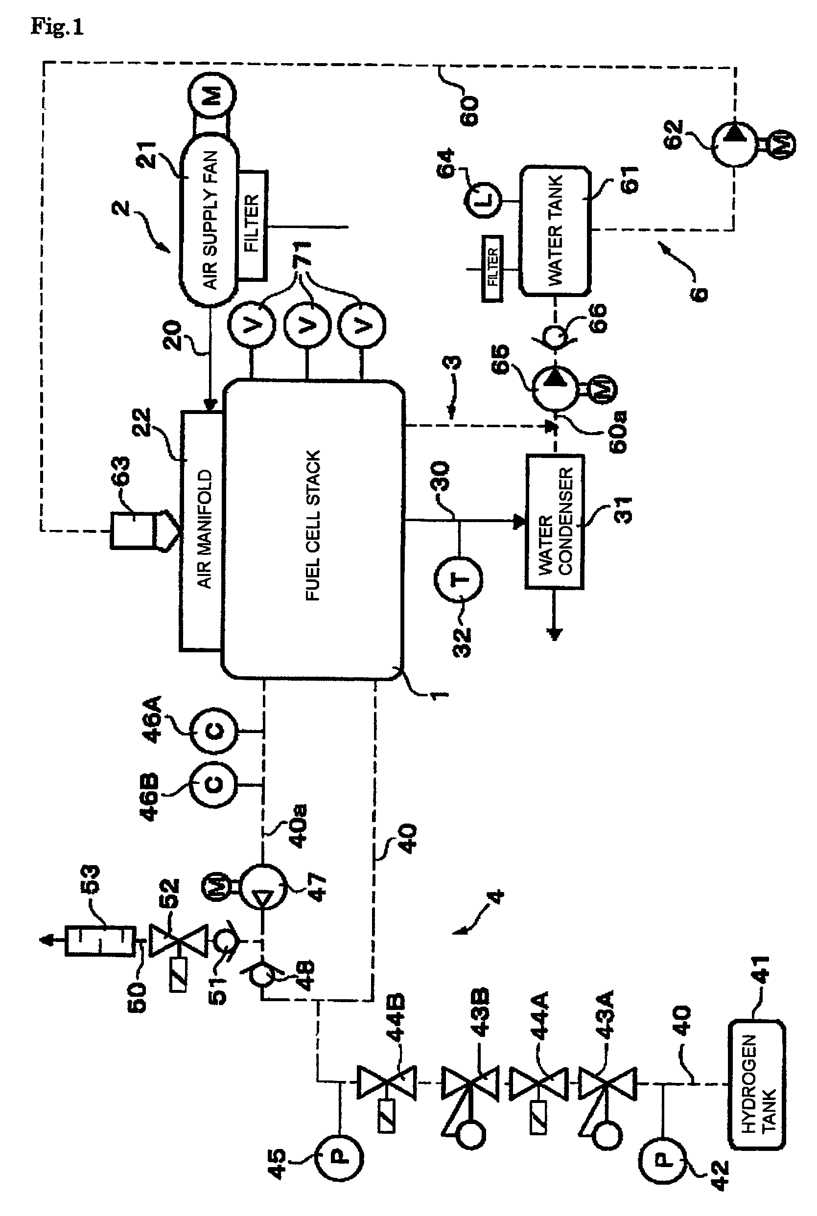
[0026]Hereinafter, embodiments of the present invention will be described with reference to the drawings. Firstly, FIGS. 1 to 7 show a first embodiment of the present invention. FIG. 1 is a view showing an exemplary structure of a fuel cell system for use in a vehicle; the fuel cell system includes a fuel cell stack 1 according to the present invention. The fuel cell system includes a fuel cell main unit with the fuel cell stack 1 as a main component, an air supply system 2 (see the solid lines in FIG. 1), and an air discharge system 3. The air supply system 2 includes an air supply fan 21 that acts as an air supply device for supplying air to the fuel cell system 1, and the air discharge system 3 includes a water condenser 31. Further, the fuel cell system also includes a fuel supply system 4 (see the two dot chain lines in FIG. 1) and a water supply system 6 (see the broken lines in FIG. 1). The fuel supply system 4 includes a hydrogen tank 41 that acts as a hydrogen supply device...
second embodiment
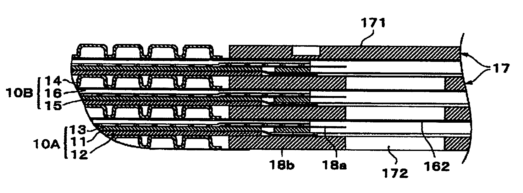
[0048]In a second embodiment shown in FIG. 8, both of the collectors 14 and 15 are made, as an example, of punching metal. Further, in this case, in order to use common material for both of the collectors 14 and 15, the dimensions of the corrugations, i.e., the height and the pitch of the corrugations, are the same as those of the fuel electrode side collector according to the first embodiment. When this structure is adopted, in order to achieve sufficient sectional area of the flow field on the air electrode side where the height of the corrugations is low, the separator 16 also has protruding corrugations 161, which protrude toward the collector 14 and which are spaced so as to match the spacing of the grooves 144 of the collector 14. As a result of this configuration, the separator base plate 16 has a corrugated plate-like shape. In the following description, the structural elements that are identical to those of the first embodiment are denoted with the same reference numerals, ...
third embodiment
[0051]In the third embodiment shown in FIG. 9, as with the second embodiment, both of the collectors 14 and 15 are made of punching metal. However, the third embodiment differs from the second embodiment in that the collector 15 of the fuel electrode side is a flat plate without any corrugations. In this example, in order to achieve sufficient sectional area of the flow fields on both sides of the air electrode and the fuel electrode, the separator base plate 16 has protruding corrugations 161 and 162 protruding toward the air electrode and the fuel electrode from a base surface of the base plate 16. The other structural elements of the third embodiment are identical to those of the second embodiment. Therefore, these structural elements are denoted with the same reference numerals, and description thereof will be omitted.
PUM
| Property | Measurement | Unit |
|---|---|---|
| thickness | aaaaa | aaaaa |
| thickness | aaaaa | aaaaa |
| electrical current | aaaaa | aaaaa |
Abstract
Description
Claims
Application Information
 - R&D
- Intellectual Property
- Life Sciences
- Materials
- Tech Scout
- Unparalleled Data Quality
- Higher Quality Content
- 60% Fewer Hallucinations
Browse by: Latest US Patents, China's latest patents, Technical Efficacy Thesaurus, Application Domain, Technology Topic, Popular Technical Reports.
© 2025 PatSnap. All rights reserved.Legal|Privacy policy|Modern Slavery Act Transparency Statement|Sitemap|About US| Contact US: help@patsnap.com


