Metallic separator for fuel cell

a fuel cell and separator technology, applied in the manufacture of cell components, final product details, cell components, etc., can solve the problems of difficult to reduce the size of a fuel cell stack consisting of several tens to several hundred unit cells, difficult to process bipolar plates with a thickness of less than 2-3 mm, and high cost of graphite plate and milling process. , to achieve the effect of excellent anti-corrosion properties and small contact resistan

Inactive Publication Date: 2007-03-29
SAMSUNG SDI CO LTD
View PDF9 Cites 3 Cited by
  • Summary
  • Abstract
  • Description
  • Claims
  • Application Information

AI Technical Summary

Benefits of technology

[0026] Aspects of the present invention provide a metallic separator for a fuel cell having excellent anti-corrosive properties and small contact resistance.

Problems solved by technology

However, graphite plate and milling processes for shaping the plates are expensive.
Further, graphite plates are typically brittle and thus, it is difficult to process bipolar plates with a thickness of less than 2-3 mm.
Due to the difficulty in decreasing the thickness of bipolar plates made of graphite, it is difficult to decrease the size of a fuel cell stack consisting of several tens to several hundreds of unit cells.
However, a metallic bipolar plate may erode under the acidic conditions that are present inside a fuel cell, and thus, an oxidized film that imposes a high electrical resistance may be easily formed.
As a result, serious problems such as membrane poisoning and increased contact resistance may occur.
Corrosion of the metallic bipolar plate not only causes defects in the bipolar plate itself, but also poisons the catalyst and electrolyte due to the diffusion of metal ions into the electrolyte membrane.
When the catalyst is poisoned, catalytic activity is decreased, and when the electrolyte is poisoned, the proton conductivity of the electrolyte is reduced, thereby resulting in deterioration of the performance of the fuel cell.
In addition, since the corroded metal dissolves, the contact between the separator and the MEA deteriorates and the electrical resistance is increased, resulting in deterioration of the performance of the fuel cell.
Thus, it has not yet been possible to use metallic bipolar plates in PEMFCs because of the likelihood of corrosion of the metal.
Problems relating to the bipolar plate or separator of a PEMFC have been described above, but such problems also occur in MCFCs, PAFCs, DMFCs, etc.

Method used


Image

  • Metallic separator for fuel cell
  • Metallic separator for fuel cell
  • Metallic separator for fuel cell

Examples


example 2

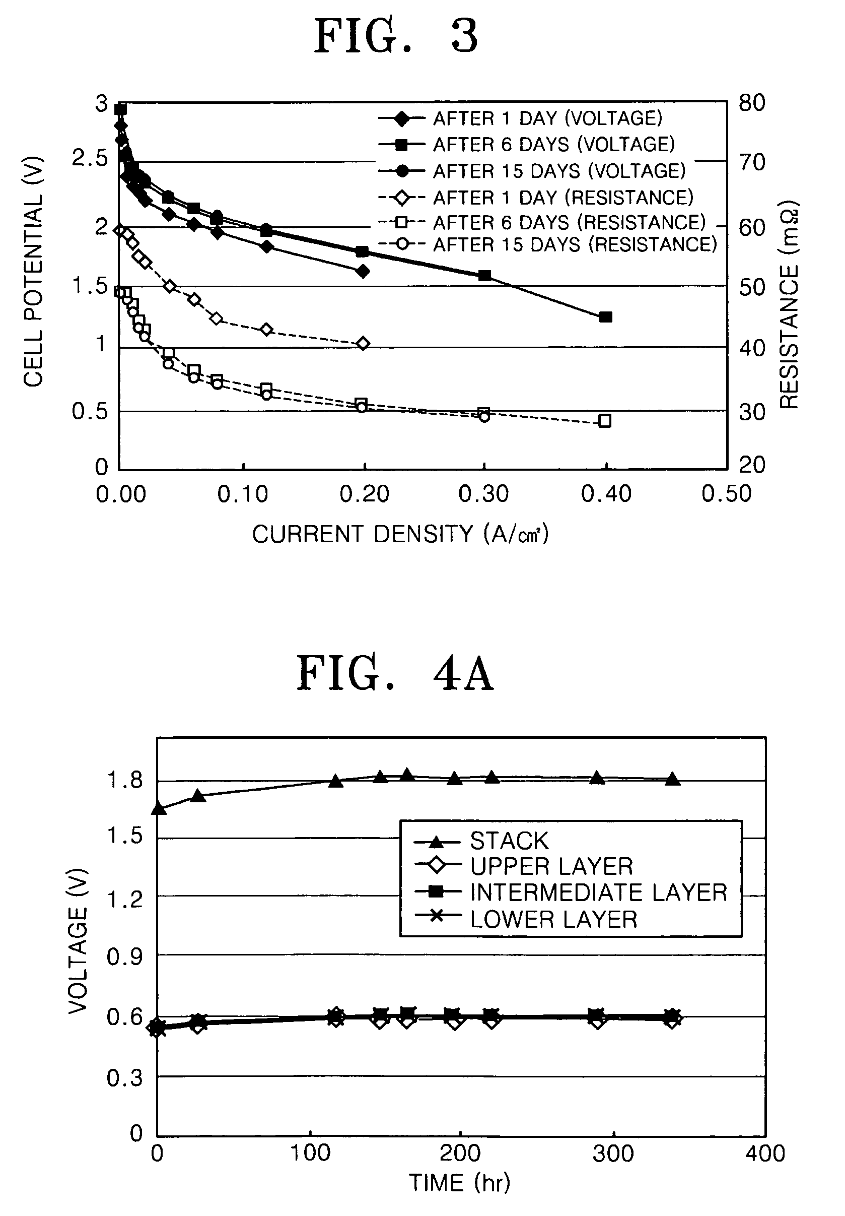
[0068] Bipolar plates and end plates were prepared with the same composition as that of the sample of Example 1, and a fuel cell stack in which 3 MEAs were stacked was prepared. A PBI (polybenzimidazole) membrane impregnated with phosphoric acid and having a thickness of 65 μm was used as an electrolyte membrane, and a Pt / C catalyst impregnated with platinum to a concentration of 1.4 mg / cm2 was used to form an anode and a cathode.

[0069] Air at a temperature of 150° C. was passed through the cathode at a rate of 1000 ml / min and hydrogen at a temperature of 150° C. was passed through the anode at a rate of 300 ml / min to observe the I-V characteristics and contact resistance of the fuel cell stack. The results are shown in FIG. 3.

[0070] Referring to FIG. 3, due to stabilization of the initial operation, the resistance decreased and the cell potential increased between the results after 1 day of operation and the results after 6 days of operation. Also, the results after 15 days of op...


PUM

PropertyMeasurementUnit
weight ratioaaaaaaaaaa
pressureaaaaaaaaaa
current densityaaaaaaaaaa

Abstract

A metallic separator for a fuel cell including 2.2 to 6.0 parts by weight of tungsten based on 100 parts by weight of stainless steel containing molybdenum, and the weight ratio of molybdenum to tungsten (Mo/W) is 0.15 to 1.60. The separator for fuel cells has excellent anti-corrosive properties and contact resistance as low as that of a metal material, and thus, a fuel cell having high efficiency can be manufactured at a reasonable cost using the separator.

Description

CROSS-REFERENCE TO RELATED APPLICATIONS [0001] This application claims the benefit of Korean Patent Application No. 2005-89471, filed on Sep. 26, 2005, in the Korean Intellectual Property Office, the disclosure of which is incorporated herein in its entirety by reference. BACKGROUND OF THE INVENTION [0002] 1. Field of the Invention [0003] Aspects of the present invention relate to a metallic separator for a fuel cell, and more particularly, to a metallic separator for a fuel cell having excellent anti-corrosive properties and a low contact resistance. [0004] 2. Description of the Related Art [0005] In a fuel cell, a fuel such as hydrogen, natural gas, methanol, or the like is oxidized to produce electrons and hydrogen ions at an anode. The hydrogen ions produced in the anode pass through an electrolyte membrane to a cathode, and the electrons produced in the anode are supplied to an external circuit through a wire. The hydrogen ions that reach the cathode are combined with the elect...

Claims


Application Information

Patent Timeline
Patent Type & Authority Applications(United States)
IPC IPC(8): H01M8/02C22C38/44
CPCC22C38/001C22C38/02Y02E60/50C22C38/44H01M8/021C22C38/04Y02P70/50H01M8/02
Inventor PARK, JUNG-OCKKIM, TAE-YOUNGKIM, KYOO-YOUNGYOO, DUCK-YOUNG
Owner SAMSUNG SDI CO LTD
Why Eureka
Try Eureka