On-board tool tracking system and methods of computer assisted surgery

a tracking system and tool technology, applied in the field of computer assisted surgery, can solve the problems of complex surgical procedures, failure of joints, complex devices that require significant time and skill to locate, etc., and achieve the effect of improving or reducing image rate, pixel or sub-pixel vision processing

Active Publication Date: 2019-03-05
BOARD OF RGT UNIV OF NEBRASKA
View PDF696 Cites 562 Cited by
  • Summary
  • Abstract
  • Description
  • Claims
  • Application Information

AI Technical Summary

Benefits of technology

[0022]In still another aspects, there is provided a system for performing computer assisted surgery, having a surgical tool having an active element corresponding to the surgical function of the tool; an on tool tracking device coupled to the tool using a housing configured to engage with at least a portion of the surgical tool; at least one camera in the housing configured to obtain imaging information related to the surgical tool and a surgical field; an output device like the display, or, optionally a projector in the housing configured to provide a projected output on or near an active element of the surgical tool; a computer having computer readable instructions stored within electronic memory for performing a computer assisted surgical procedure using data at least partially obtained from the on tool tracking device and to provide an output for use during a step of the surgery. When the system includes a projector within the OTT capabilities, the projector further comprising one or more of the following: projection capability to project an output on a portion of the patient's anatomy, a surface within the surgical scene, an electronic device, or other object within the projector output range. In one configuration, the computer is in the housing in another the computer is separated from the on tool tracking device and connected via a wired or a wireless connection. In still further aspects, the system includes one or more of the computer readable instructions for performing any of the CAS mode select methods described above. In still further aspect, the system may include the on tool tracking device having one or more of the elements described above. The system may adapted and configured for use with one or more reference frames and associated methods described herein. In a still further aspect, the system is adapted and configured for use in combination with a tactile feedback mechanism described herein.

Problems solved by technology

Many surgical procedures are complex procedures requiring numerous alignment jigs and intricate soft tissue procedures.
If the alignment is inaccurate, the misalignment can eventually lead to failure of the joint, requiring the complex task of replacing one or more portions of the knee prosthesis.
The jigs are complex devices that require significant time and skill to locate and attach on the patient during the surgical procedure.

Method used


Image

  • On-board tool tracking system and methods of computer assisted surgery
  • On-board tool tracking system and methods of computer assisted surgery
  • On-board tool tracking system and methods of computer assisted surgery

Examples


Embodiment Construction

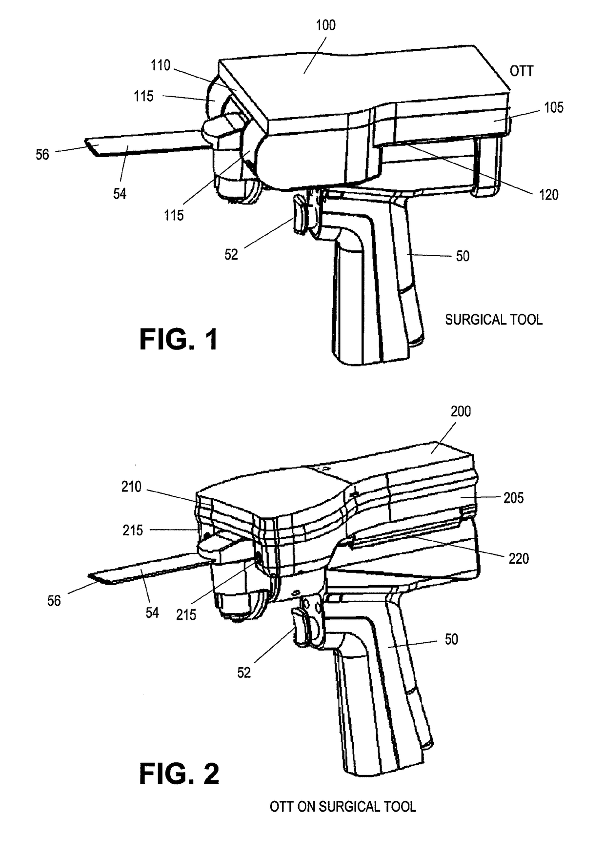
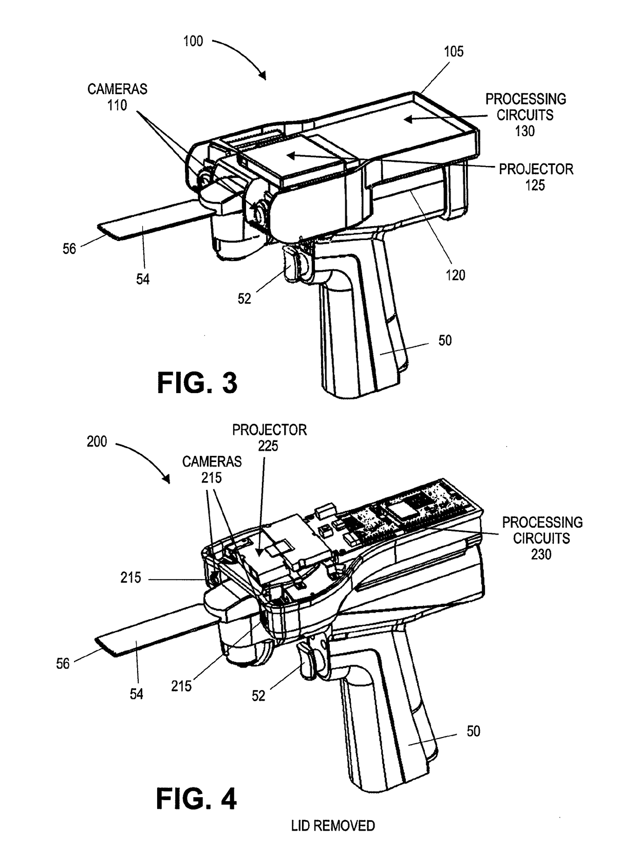
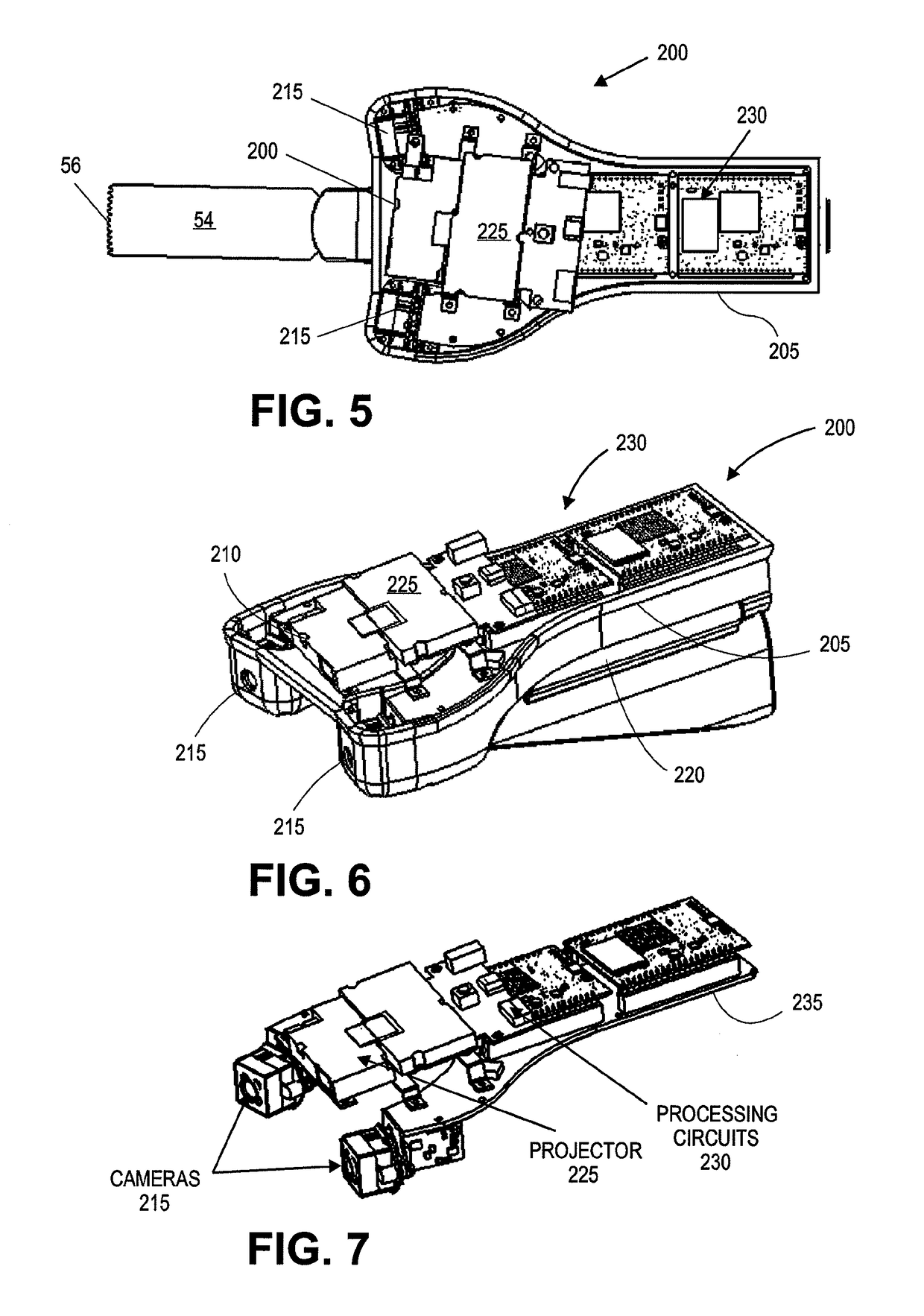
[0070]The present invention is a system for performing computer assisted orthopedic surgery and novel tools for operating that system. The present invention overcomes limitations of current computer assisted surgery systems by optionally combining all elements of computer assisted surgery (tools, displays and tracking) into a single smart instrument. The instrument does not rely on an external navigation system but the tool contains all the tracking equipment on the tool itself in a self-contained assembly. As a result, the overall system is significantly less complicated, less intrusive to the surgeon and easy to integrate into existing practices in orthopedic surgery.

[0071]By way of overview, the system is comprised of principal subsystems. The first is the tool itself, which is used to carry a standalone on tool tracking device or modified to contain the subsystems or elements of the subsystems to provide On-Tool Tracking (OTT) functionality. The modifications can be simple, such...


PUM


Abstract

A number of improvements are provided relating to computer aided surgery utilizing an on tool tracking system. The various improvements relate generally to both the methods used during computer aided surgery and the devices used during such procedures. Other improvements relate to the structure of the tools used during a procedure and how the tools can be controlled using the OTT device. Still other improvements relate to methods of providing feedback during a procedure to improve either the efficiency or quality, or both, for a procedure including the rate of and type of data processed depending upon a CAS mode.

Description

CROSS REFERENCE TO RELATED APPLICATIONS[0001]This application is a National Stage Entry of PCT Application No. PCT / US2012 / 044486, filed Jun. 27, 2012 which claims the benefit under 35 U.S.C. § 119 of U.S. Provisional Patent Application No. 61 / 501,489, filed Jun. 27, 2011, titled “SYSTEM FOR COMPUTER ASSISTED NAVIGATION AND CONTROL OF A POWER TOOL.” These applications are herein incorporated by reference in their entireties.STATEMENT AS TO FEDERALLY SPONSORED RESEARCH[0002]This invention was made with Government support under Grant No. W911QY-10-C-0178, awarded by the Army Natick Soldier System Center. The Government has certain rights in the invention.INCORPORATION BY REFERENCE[0003]All publications and patent applications mentioned in this specification are herein incorporated by reference to the same extent as if each individual publication or patent application was specifically and individually indicated to be incorporated by reference.FIELD[0004]The present invention relates to ...

Claims


Application Information

Patent Timeline
Patent Type & Authority Patents(United States)
IPC IPC(8): A61B34/20A61B34/00A61B17/14A61B34/32A61B34/30A61B17/16A61B17/17A61B90/00A61B34/10
CPCA61B17/1703A61B17/142A61B17/1626A61B17/1675A61B17/1764A61B34/20A61B34/32A61B34/76A61B34/30A61B2090/371A61B2034/102A61B2034/2057A61B2090/064A61B2090/366A61B17/14
Inventor HAIDER, HANIAL-SHAWI, IBRAHIMBARRERA, OSVALDO ANDRES
Owner BOARD OF RGT UNIV OF NEBRASKA
Why Eureka
Try Eureka