
System and method of cooling by latent energy transfer

a technology of latent energy and cooling system, applied in ventilation systems, lighting and heating apparatus, heating types, etc., can solve the problems of ineffective use of cooling towers alone and fall in the temperature of transfer fluids, and achieve the effect of reducing the absolute humidity of ambient air and reducing the temperature of ambient air in the wet bulb

Active Publication Date: 2019-03-05
INTEX HLDG
View PDF16 Cites 0 Cited by
  • Summary
  • Abstract
  • Description
  • Claims
  • Application Information

AI Technical Summary

Benefits of technology

The patent aims to provide a system that can maintain a constant temperature for a fluid by using a second tank to hold a warmer fluid and prevent it from mixing with the fluid in the first tank during a certain period of time. Additionally, the patent also describes a method to produce dried air by reducing the humidity in the ambient air.

Problems solved by technology

This method is used, for example, in cooling towers, typically combined with a heat exchanger to transfer thermal energy from a transfer fluid, in the heat exchanger, to the evaporating water droplets, resulting in a fall in the temperature of the transfer fluid.
However, with indirect contact cooling tower technology, heat transfer across a heat exchanger always results in a temperature of the transfer fluid at least several degrees above the prevailing wet bulb temperature.
The use of a cooling tower alone is ineffective in many climates as the wet bulb temperatures do not fall low enough, for sufficiently long periods of time in summer, to produce a usefully cooled transfer fluid.

Method used

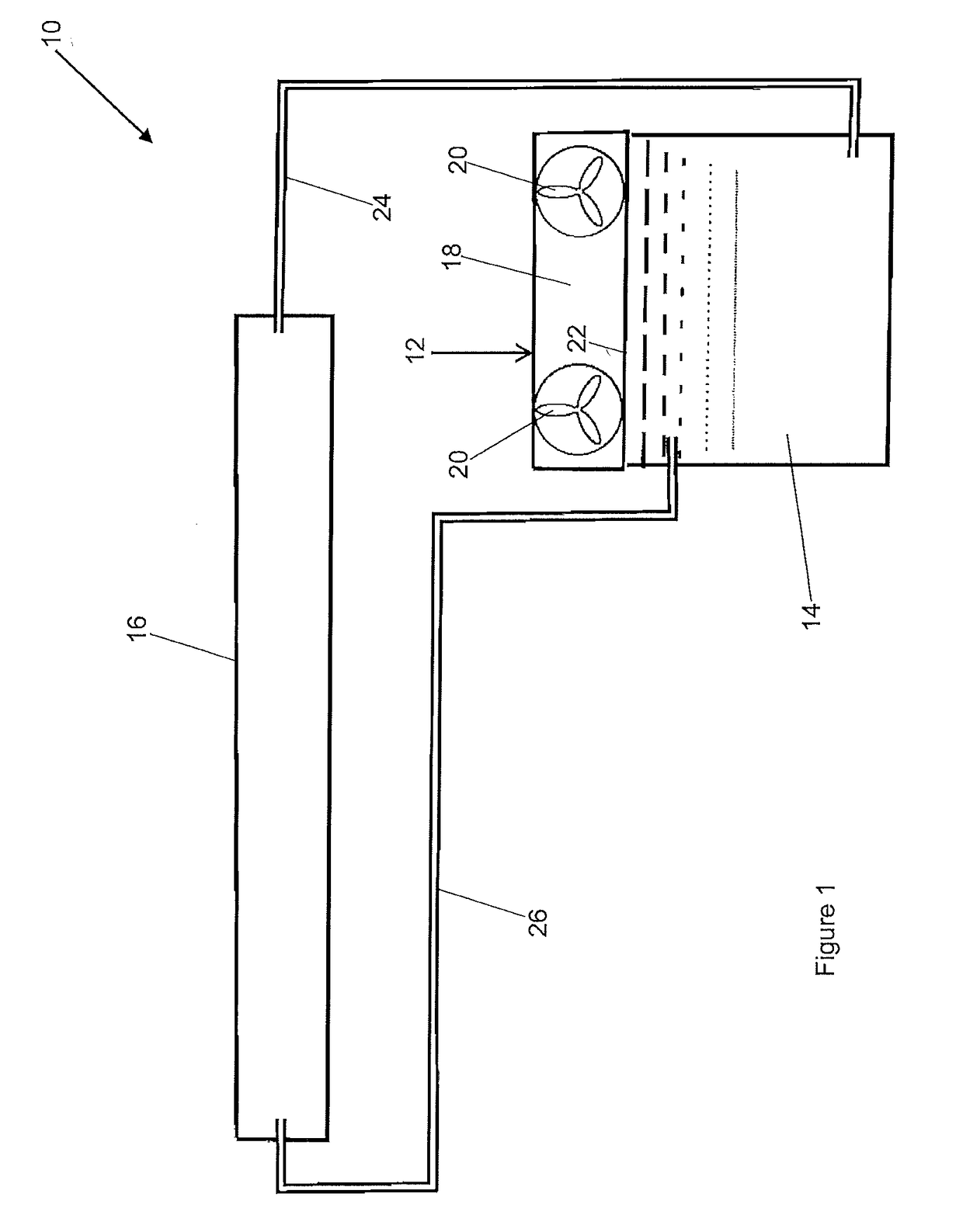
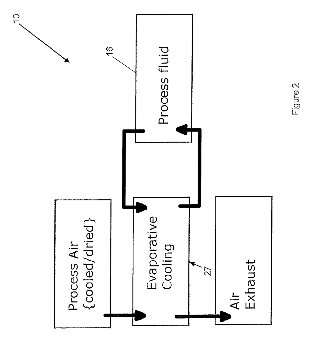
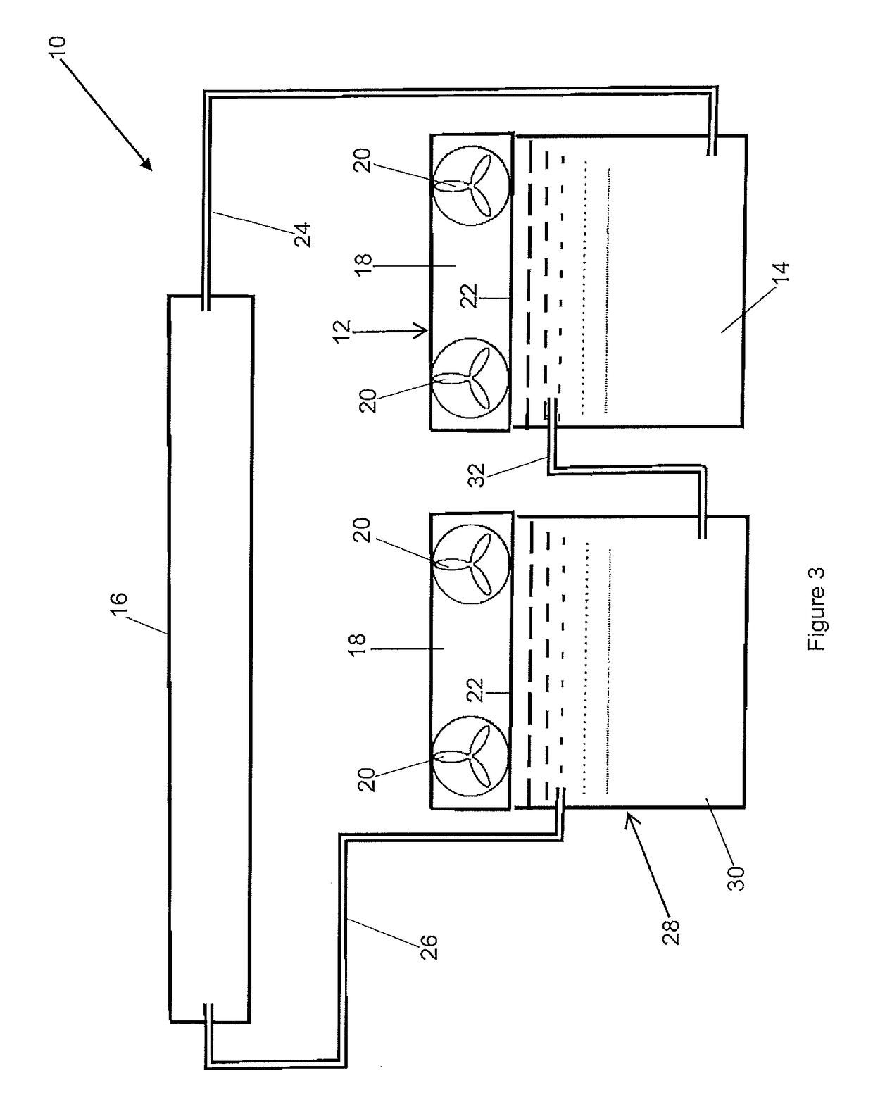

Image

  • System and method of cooling by latent energy transfer
  • System and method of cooling by latent energy transfer
  • System and method of cooling by latent energy transfer

Examples


Embodiment Construction

[0062]The following detailed description of the invention refers to the accompanying drawings. Although the description includes exemplary embodiments, other embodiments are possible, and changes may be made to the embodiments described without departing from the spirit and scope of the invention. Wherever possible, the same reference numbers will be used throughout the embodiments and the following description to refer to the same and like parts.

[0063]It is to be understood that a cooling system and method embodying the present invention may be used in a number of different applications requiring cooled fluid or air to be provided to a location or a process. By way of example, the cooling of fluid for subsequent use in a process used to cool a space in a building interior is described herein. However, the present invention has other applications, including cooling other interiors or internal (fully or partially enclosed) areas or other processes including industrial processes.

[0064...


PUM


Abstract

The present invention relates to a system and method of cooling by latent energy transfer and, in particular, to cool a fluid by discharging unwanted low temperature thermal energy to a surrounding ambient environment utilizing a fluid evaporation process involving permitted or forced ventilation of air across a surface area of a heat transfer fluid. The invention further relates to an air treatment system utilizing the cooled heat transfer fluid for cooling air and for supplying ventilation air to the evaporation process. A body of liquid is cooled close to the prevailing wet bulb temperature, discharging unwanted thermal energy to the surroundings, rendering the liquid suitable as a cooling medium for removing unwanted thermal energy from a location or in a process.

Description

FIELD OF THE INVENTION[0001]The present invention relates to a system and method of cooling by latent energy transfer and, in particular, to cool a fluid by discharging unwanted low temperature thermal energy to a surrounding ambient environment utilising a fluid evaporation process involving permitted or forced ventilation of air across a surface area of a heat transfer fluid. The invention further relates to an air treatment system utilising the cooled heat transfer fluid for cooling air and for supplying ventilation air to the evaporation process. A body of liquid is cooled close to the prevailing wet bulb temperature, discharging unwanted thermal energy to the surroundings, rendering the liquid suitable as a cooling medium for removing unwanted thermal energy from a location or in a process.BACKGROUND OF THE INVENTION[0002]A reliable method of rejecting unwanted thermal energy to ambient is frequently required, for example, as part of many industrial and manufacturing processes,...

Claims


Application Information

Patent Timeline
Patent Type & Authority Patents(United States)
IPC IPC(8): F24F12/00F24F6/02F24F5/00F24F3/14
CPCF24F12/002F24F3/14F24F5/0007F24F5/0035F24F6/02F24F5/0017Y02E60/147Y02E60/14
Inventor DAVIES, ROGER PHILIP
Owner INTEX HLDG
Learn More