
Light integration module and optical system employing same

a technology of light integration module and optical system, applied in the direction of instruments, fibre light guides, mechanical devices, etc., can solve the problems of degrading luminous flux and affecting the appearance of the surface, and achieve the effect of a larger surface area

Active Publication Date: 2019-03-05
DELTA ELECTRONICS INC
View PDF13 Cites 0 Cited by
  • Summary
  • Abstract
  • Description
  • Claims
  • Application Information

AI Technical Summary

Benefits of technology

The solution effectively prevents damage to the anti-reflection coating, maintaining high transmittance and reducing light loss, even as the system ages, by distributing dust evenly across the increased incident area.

Problems solved by technology

The surface temperature where the dust sticks will be increased due to the heat absorption of the dust, such that the AR coating could be damaged.
However, this will degrade luminous flux due to lower light transmittance of the light integration rod 12.

Method used


Image

  • Light integration module and optical system employing same
  • Light integration module and optical system employing same
  • Light integration module and optical system employing same

Examples


Embodiment Construction

[0022]The present invention will now be described more specifically with reference to the following embodiments. It is to be noted that the following descriptions of preferred embodiments of this invention are presented herein for purpose of illustration and description only. It is not intended to be exhaustive or to be limited to the precise form disclosed.

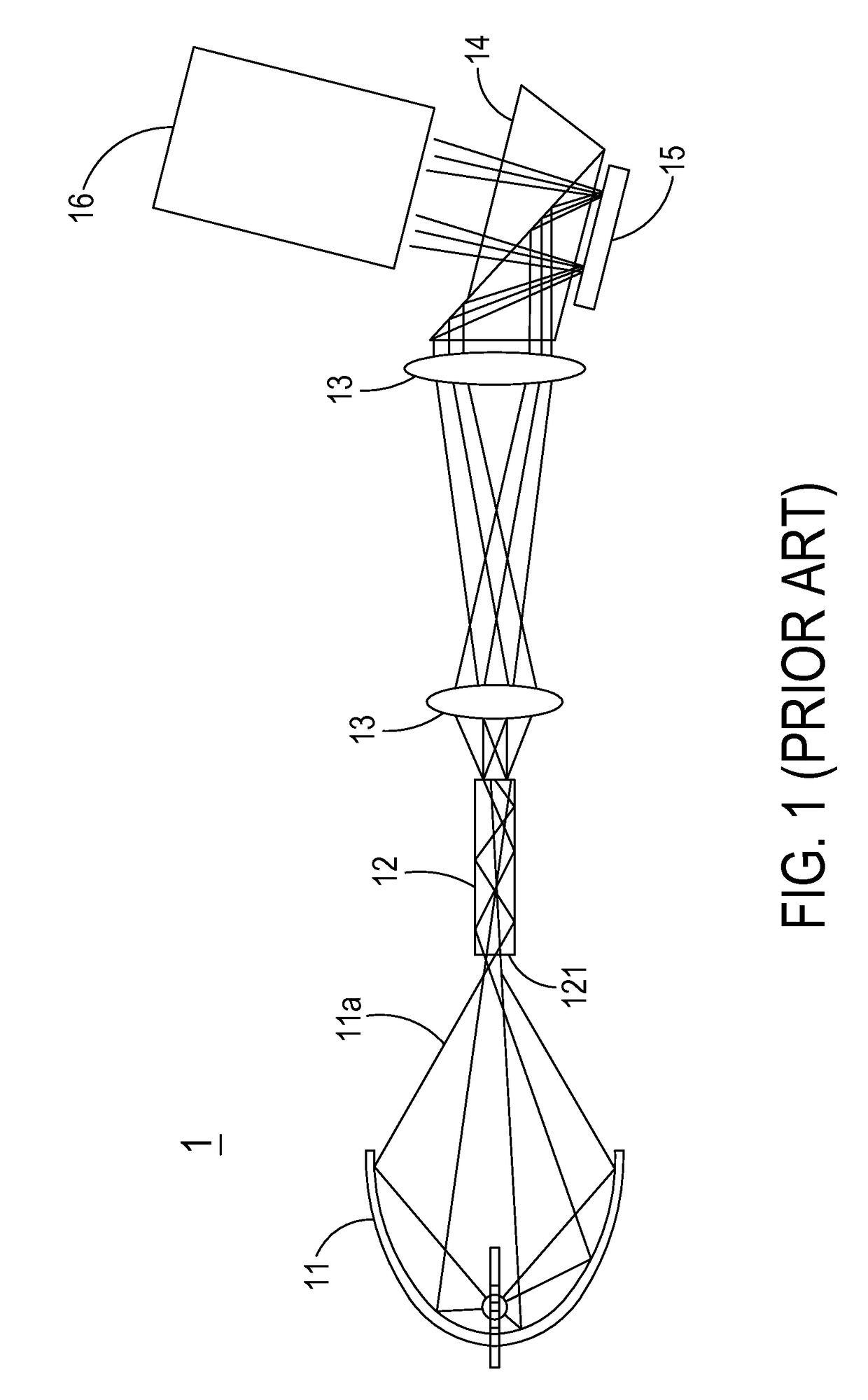
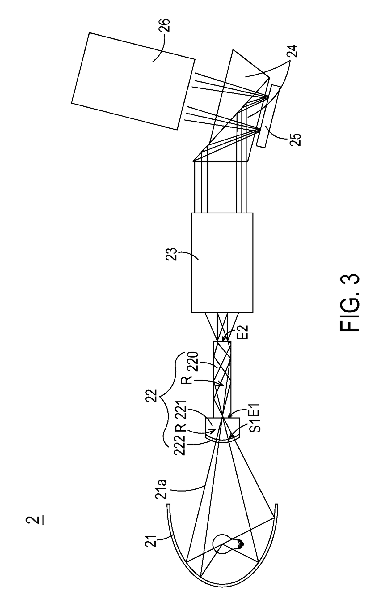
[0023]Please refer to FIG. 3, FIG. 4A, FIG. 4B, FIG. 4C, FIG. 4D and FIG. 4E. FIG. 3 is a schematic view illustrating the light path from the light source to the projection lens in an optical system of the present invention; FIG. 4A is a schematic view illustrating the light integration module with a plano-convex lens of the present invention; FIG. 4B is a schematic view illustrating the light integration module with a plano-plano glass plate of the present invention; FIG. 4C is another schematic view illustrating the light integration module with a plano-convex lens of the present invention; FIG. 4D is another schematic view ill...


PUM

PropertyMeasurementUnit
reflectivityaaaaaaaaaa
cross-sectional areaaaaaaaaaaa

Abstract

An optical system comprises a light source and a light integration module, which comprises a light integration rod, an optical assembly and an anti-reflection coating. The light integration rod has an entrance, which is covered by the optical assembly. The optical assembly has a transparent surface, and a surface area of the transparent surface is greater than a cross-sectional area of the entrance of the light integration rod. The anti-reflection coating is formed on the transparent surface. After an incident light is transmitted through the anti-reflection coating, it is transmitted through the optical assembly along a light path, and then outputted to the entrance of the light integration rod.

Description

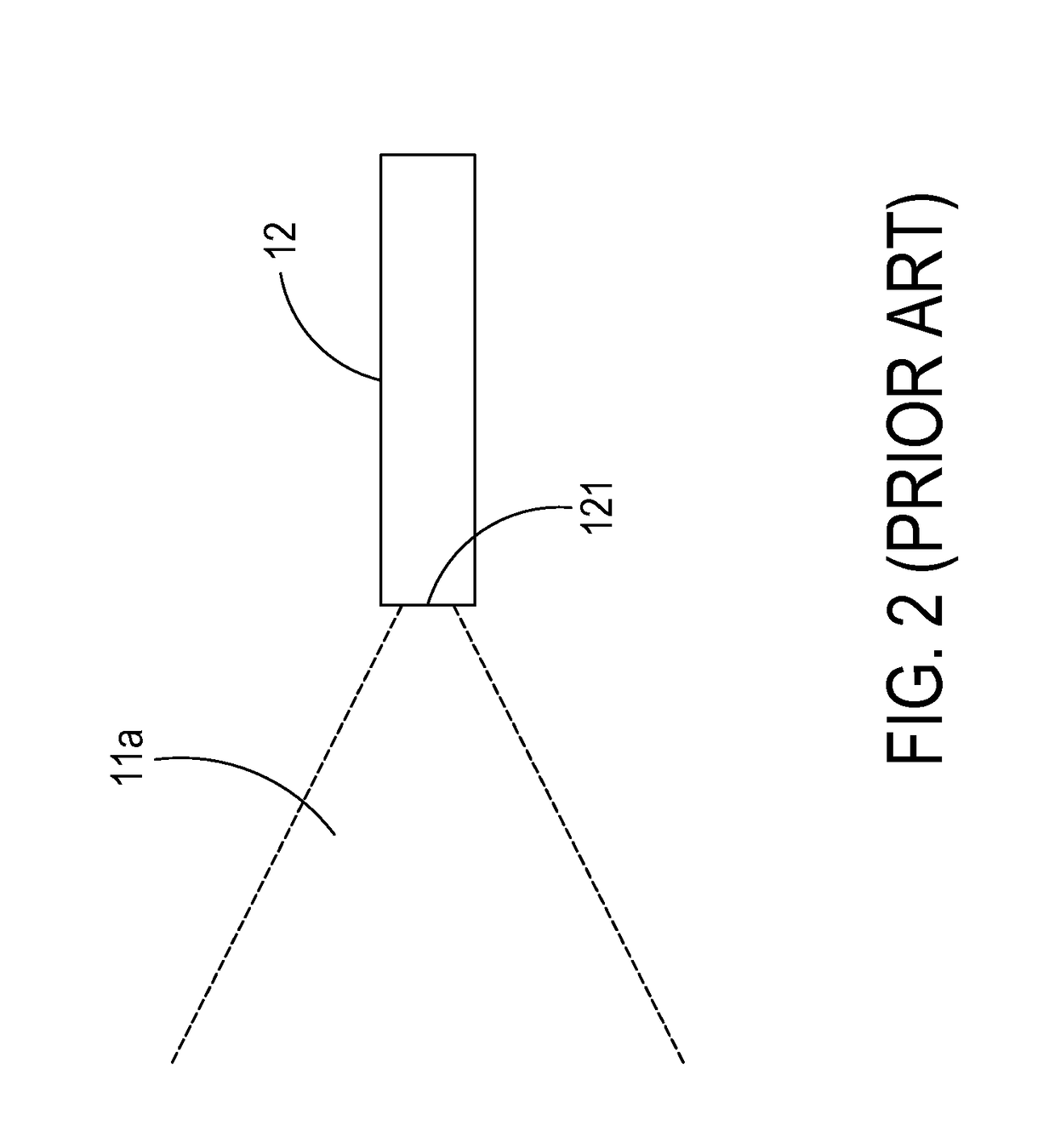
CROSS-REFERENCE TO RELATED APPLICATION[0001]This application claims the benefit of U.S. Provisional Application No. 61 / 928,087 filed on Jan. 16, 2014, and entitled “LIGHT INTEGRATION MODULE AND OPTICAL PROJECTION SYSTEM EMPLOYING SAME”, the entirety of which is hereby incorporated by reference.FIELD OF THE INVENTION[0002]The present invention relates to a light integration module, and more particularly to a light integration module capable of avoiding dust being stuck to the entrance of the light integration rod of the light integration module and the optical system employing same.BACKGROUND OF THE INVENTION[0003]In recent years, a variety of projectors have been widely used in various video applications. For example, the projectors can be used for making presentations, holding meetings or giving lectures in classrooms, board rooms, conference rooms or home theaters. By a projector, an image signal from an image signal source can be enlarged and shown on a projection screen.[0004]FI...

Claims


Application Information

Patent Timeline
Patent Type & Authority Patents(United States)
IPC IPC(8): F21V8/00G02B6/42G02B1/11G02B27/00
CPCG02B27/0006G02B6/4207G02B1/11G02B6/0006
Inventor WANG, BOR
Owner DELTA ELECTRONICS INC
Learn More