Soil compaction mitigation assembly and method

a technology of soil compaction and assembly, applied in soil loosening devices, agriculture, agricultural tools and machines, etc., can solve the problems of soil compaction, reduce the ability of soil to absorb water and air, reduce crop yield, etc., and achieve the effect of cost reduction

Active Publication Date: 2019-03-19
TRIBINE IND
View PDF15 Cites 21 Cited by
  • Summary
  • Abstract
  • Description
  • Claims
  • Application Information

AI Technical Summary

Benefits of technology

[0007]The most advantageous mechanism to remove axle load tracks and the underlying compaction is a system, which is integrated into the vehicle that is forming the tracks, such as, for example, a tractor, grain harvester, or grain transporter. The compaction mitigation method or tool should not add to the compaction or throw soil sideways, such as does a disc harrow. The compaction mitigation system should leave the soil nearly level and containing as much air or as “fluffy” as possible. In the case of harvesting, it should mix crop residue into the soil and chop off weeds. It should be effective regardless of the shape of the compacted tracks resultant of the tire or crawler track lugs. The general shape of a compacted track is elliptical with the highest level of compaction in the center of the ellipse. Therefore, the center of the ellipse requires the deepest penetration by the compaction mitigation tool. Mitigating the compaction track during the harvesting process would result in a major cost reduction by eliminating the need to deep rip the entire harvested field.

Problems solved by technology

Even standing water can cause soil compaction.
Soil compaction reduces the ability of the soil to absorb water and air and, therefore, reduces crop yields and increases soil erosion.
An untended compacted wheel track or rut will fill with water and hold it for a long period of time until it is tilled.
This is a major problem for a farmer using the no-till growing system.

Method used


Image

  • Soil compaction mitigation assembly and method
  • Soil compaction mitigation assembly and method
  • Soil compaction mitigation assembly and method

Examples


Embodiment Construction

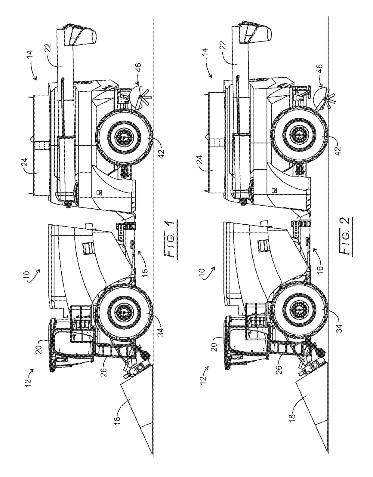
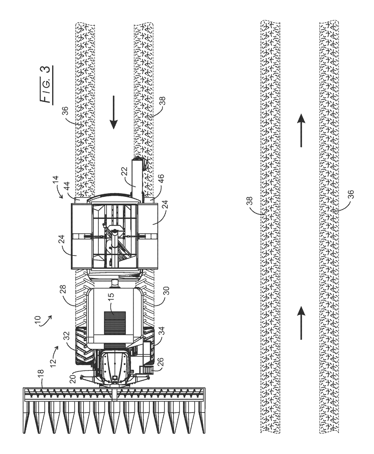
[0026]Referring initially to FIGS. 1 and 2, an articulated harvester, 10, consists of a powered PPU (crop processing power unit), 12, a rear grain cart, 14, and an articulation joint, 16, that connects PPU 12 with rear grain cart 14. The details of articulation joint 16 are disclosed in commonly owned application Ser. No. 14 / 946,827 filed Nov. 20, 2015. PPU 12 carries a grainhead, 18, operator's cab, 20, grain cleaning and handling assembly, and engines. PPU 12 is devoid of any grain storage, such being exclusive in rear grain cart 14. While both PPU 12 and rear grain cart 14 are shown being carried by wheel assemblies, one or both could be tracked. A screened air inlet, 15, is located atop PPU 12 where the air likely is the cleanest around harvesting combine 10. The operator is granted access to cab 20 by a stair assembly, 26, that extends upwardly from just above the ground and is more fully disclosed in commonly owned application Ser. No. 15 / 654,786, filed Jul. 20, 2017, now aban...


PUM


Abstract

Disclosed is an assembly for mitigating soil compacted by wheels or belts of a vehicle moving over soil and carried by the vehicle. The assembly operates with a series of blades affixed to a rotatable shaft and displaying an elliptical pattern. A hood confines about the top half of the blades and spans about the width of the assembly. A motor rotates the rotatable shaft. A mounting assembly mounts the assembly to the vehicle behind and in alignment with the vehicle wheels or belts. A cylinder assembly reversibly moves the assembly from a home position downwardly into compacted soil for its mitigation.

Description

CROSS-REFERENCE TO RELATED APPLICATIONS[0001]This application claims benefit of provisional application 62 / 363,381, filed Jul. 18, 2016.STATEMENT REGARDING FEDERALLY SPONSORED RESEARCH[0002]Not applicable.BACKGROUND[0003]The present disclosure relates to mitigation of soil compaction caused by heavy vehicles and more particularly to self-soil compaction by the heavy vehicles that cause such soil compaction, such as typified by a harvesting combine.[0004]Soil compaction, as we know it today, is caused primarily by heavily laden vehicles supported by tires or crawler lugged belts passing over the soil, and certain tillage tools, such as a disc, which compresses the soil as it pushes the soil sideways. Even standing water can cause soil compaction. Soil compaction reduces the ability of the soil to absorb water and air and, therefore, reduces crop yields and increases soil erosion. The degree to which soil is compacted by a specific weighted axle passing over it is affected by the rati...

Claims


Application Information

Patent Timeline
Patent Type & Authority Patents(United States)
IPC IPC(8): A01B37/00A01B35/28A01B35/16A01B77/00A01B33/02
CPCA01B37/00A01B35/16A01B35/28A01B77/00A01B33/021
Inventor DILLON, BEN N.
Owner TRIBINE IND
Why Eureka
Try Eureka