
Heat resistant structure for shaft retainer, and actuator

a technology of heat-resistance structure and shaft retainer, which is applied in the direction of bearing cooling, sliding contact bearings, mechanical devices, etc., can solve the problems of loss of function of components composed of materials with low heat-resistance capability, and achieve the effect of enhancing the heat-resistance capability of shaft retainers

Inactive Publication Date: 2019-03-19
MITSUBISHI ELECTRIC CORP
View PDF34 Cites 0 Cited by
  • Summary
  • Abstract
  • Description
  • Claims
  • Application Information

AI Technical Summary

Benefits of technology

The invention provides a shaft retainer with improved heat resistance. By adding a boss with high heat conductivity around the bushing and forming a heat insulating layer between them, the retainer can withstand higher temperatures while maintaining its compact design.

Problems solved by technology

In a situation in which a shaft retainer of actuators is used under a relatively high temperature environment, heat that is transferred through the shaft retainer from the outside to the inside of the actuator or other devices may cause troubles in the operation of a driving part such as a motor or the like, or lead to loss of function of a component composed of a material with low heat-resistance capability, for example.

Method used


Image

  • Heat resistant structure for shaft retainer, and actuator
  • Heat resistant structure for shaft retainer, and actuator
  • Heat resistant structure for shaft retainer, and actuator

Examples


embodiment 1

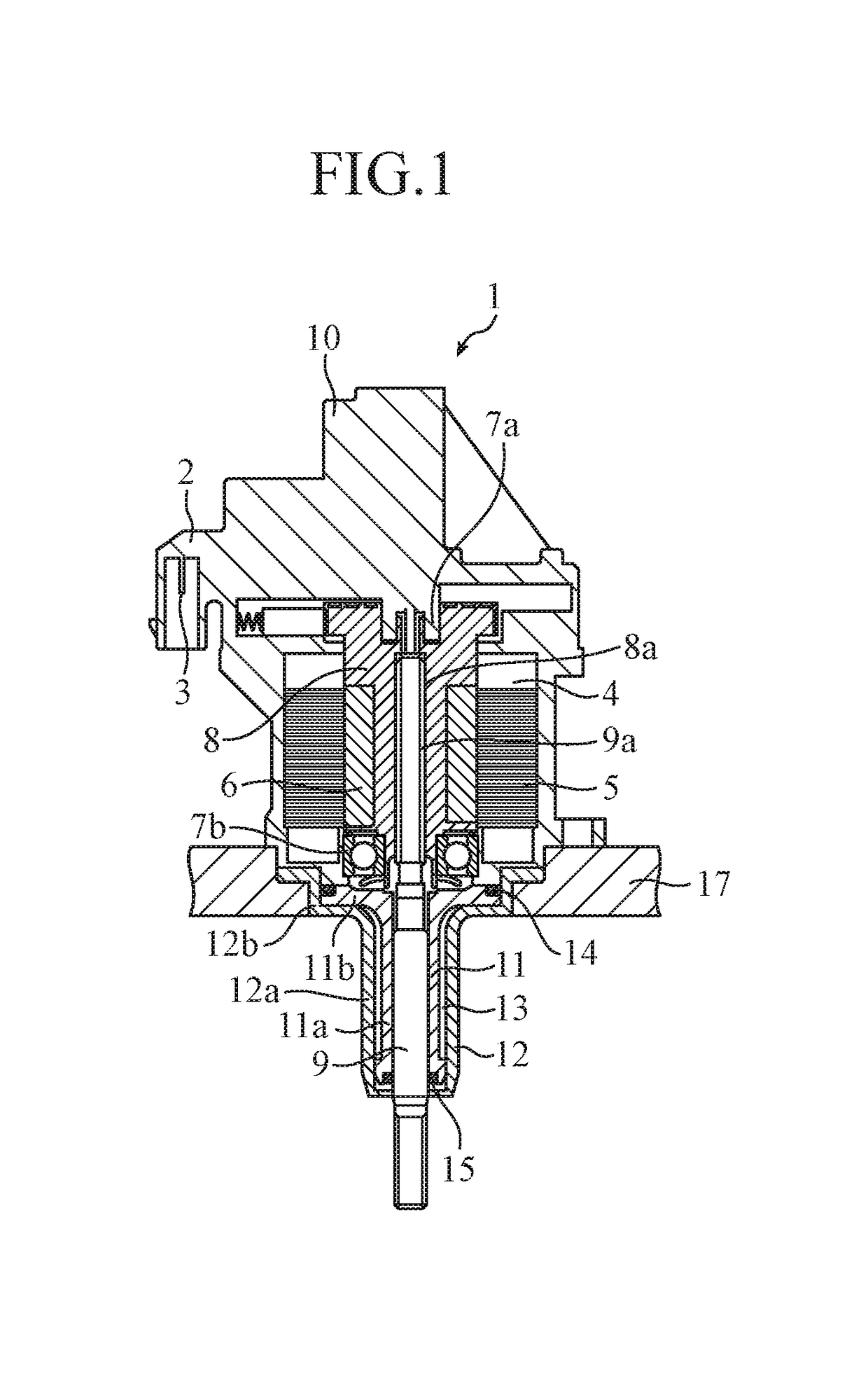
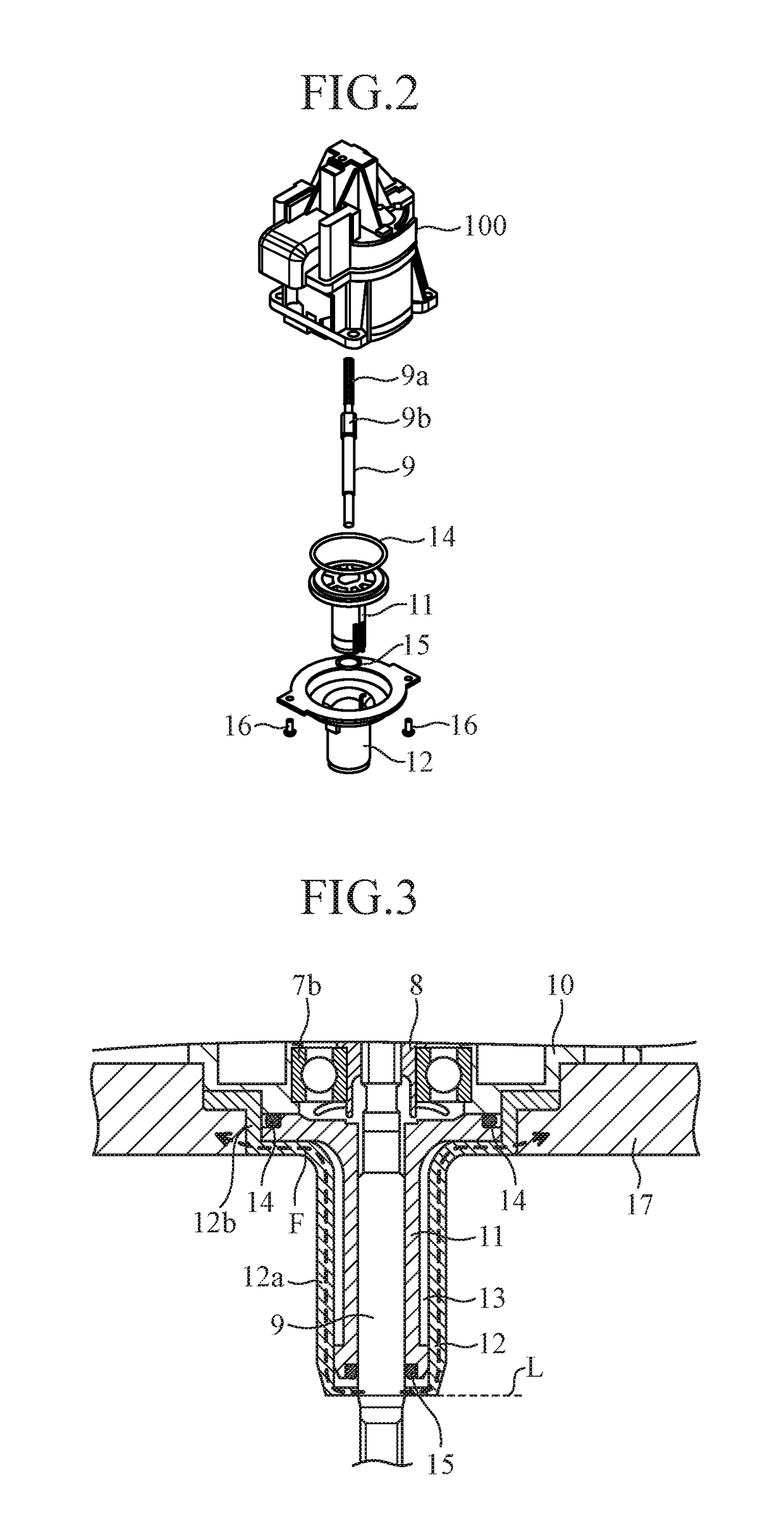
[0015]FIG. 1 is a cross-sectional view of an actuator 1 provided with a heat resistant structure for a shaft retainer according to Embodiment 1 of the invention. FIG. 2 is an exploded perspective view of the actuator 1. Hereinafter, description will be made assuming that the actuator is one employing an electrically controlled motor, though another type of actuator, such as a pressure actuator, may be used.

[0016]By applying a voltage to a terminal 3 provided in an external input / output connector 2 of the actuator 1, an electric current flows in a coil 5 wound around a stator 4 to magnetize a plurality of poles of the stator 4 into an N or S pole. A substantially cylindrical rotor 8 includes an NS-magnetized magnet 6, and the upper and lower ends of the rotor 8 are retained respectively by a bushing 7a and a bearing 7b. In response to the NS magnetization of the stator 4, the rotor 8 rotates.

[0017]The interior of the rotor 8 is provided with a female screw as a screw mechanism 8a for...


PUM

PropertyMeasurementUnit
heat resistantaaaaaaaaaa
heat conductivityaaaaaaaaaa
heataaaaaaaaaa

Abstract

A boss is provided around the periphery of a bushing that is penetrated by a shaft, which moves inside the bushing in the axial direction of the shaft. The boss retains the bushing and the shaft moving inside the bushing, and has a heat conductivity that is higher than that of the bushing. An air gap is provided between the bushing and the boss.

Description

TECHNICAL FIELD[0001]The present invention relates to a shaft retainer for retaining a shaft in such a manner that the shaft is movable in the axis direction of the shaft, and also to an actuator provided with such a shaft retainer.BACKGROUND ART[0002]A variety of mechanical configurations that retain a shaft in such a manner that the shaft is movable in the axis direction are known. Examples of the configurations include, e.g., a shaft retainer of a linear motion actuator. In a situation in which a shaft retainer of actuators is used under a relatively high temperature environment, heat that is transferred through the shaft retainer from the outside to the inside of the actuator or other devices may cause troubles in the operation of a driving part such as a motor or the like, or lead to loss of function of a component composed of a material with low heat-resistance capability, for example. Accordingly, various efforts have been made to prevent heat transfer from the outside to the...

Claims


Application Information

Patent Timeline
Patent Type & Authority Patents(United States)
IPC IPC(8): F16C29/02F16J15/16F16C37/00F16C33/02F16C33/20F16C33/12F16C17/22
CPCF16C29/02F16C17/22F16C33/125F16C33/20F16C37/00F16J15/162F16C33/205F16C2300/54F16C2202/20F16C2208/10
Inventor SEIMA, NOBUHIRO
Owner MITSUBISHI ELECTRIC CORP
Learn More