Tooling for use during heat treatment to support a preform made of powder

a technology of heat treatment and support, which is applied in the field of applying heat treatment to preforms, can solve the problems of increasing the quantity of powder needed, the cost, and the time for fabricating each part, and achieves the effect of shrinkage amplitude and speed

Active Publication Date: 2019-03-26
SN DETUDE & DE CONSTR DE MOTEURS DAVIATION S N E C M A
View PDF21 Cites 0 Cited by
  • Summary
  • Abstract
  • Description
  • Claims
  • Application Information

AI Technical Summary

Benefits of technology

[0012]A main object of the present invention is thus to mitigate such drawbacks by providing tooling for acting during heat treatment to support a preform of a three-dimensional part obtained by shaping a metal or ceramic powder, the preform presenting at least one bearing surface on which it can rest and at least one suspended surface that is suspended relative to the bearing surface, the tooling comprising a tray, and a plurality of blocks arranged on the tray and each having at least one surface for supporting the preform, the blocks being suitable for moving relative to one another by sliding on the tray between a first position in which the blocks are spaced apart from one another and together define a first volume, and a second position in which the blocks together define a second volume that is smaller than the first volume.
[0013]The tooling of the invention is remarkable firstly in that it is reusable and it can be used for fabricating a plurality of three-dimensional parts of the same shape in succession. Furthermore, each block has a surface that is to come into contact with the preform that generally lies at an angle in the range 0° to 90° relative to the support tray. For parts that have a surface that is suspended (or in other words cantilevered-out), such a support surface enables the preform to be supported during heat treatment, and thus avoid it creeping under its own weight. The blocks are also suitable for moving relative to one another by sliding on the sintering tray that supports them, so as to accompany the shrinkage of the preform during the heat treatment (the shrinkage of the part is generally uniform and isotropic). Specifically, the blocks may move between two positions:

Problems solved by technology

The use of such a support increases considerably the quantity of powder that is needed, the cost, and the time for fabricating each part.

Method used


Image

  • Tooling for use during heat treatment to support a preform made of powder
  • Tooling for use during heat treatment to support a preform made of powder
  • Tooling for use during heat treatment to support a preform made of powder

Examples


first embodiment

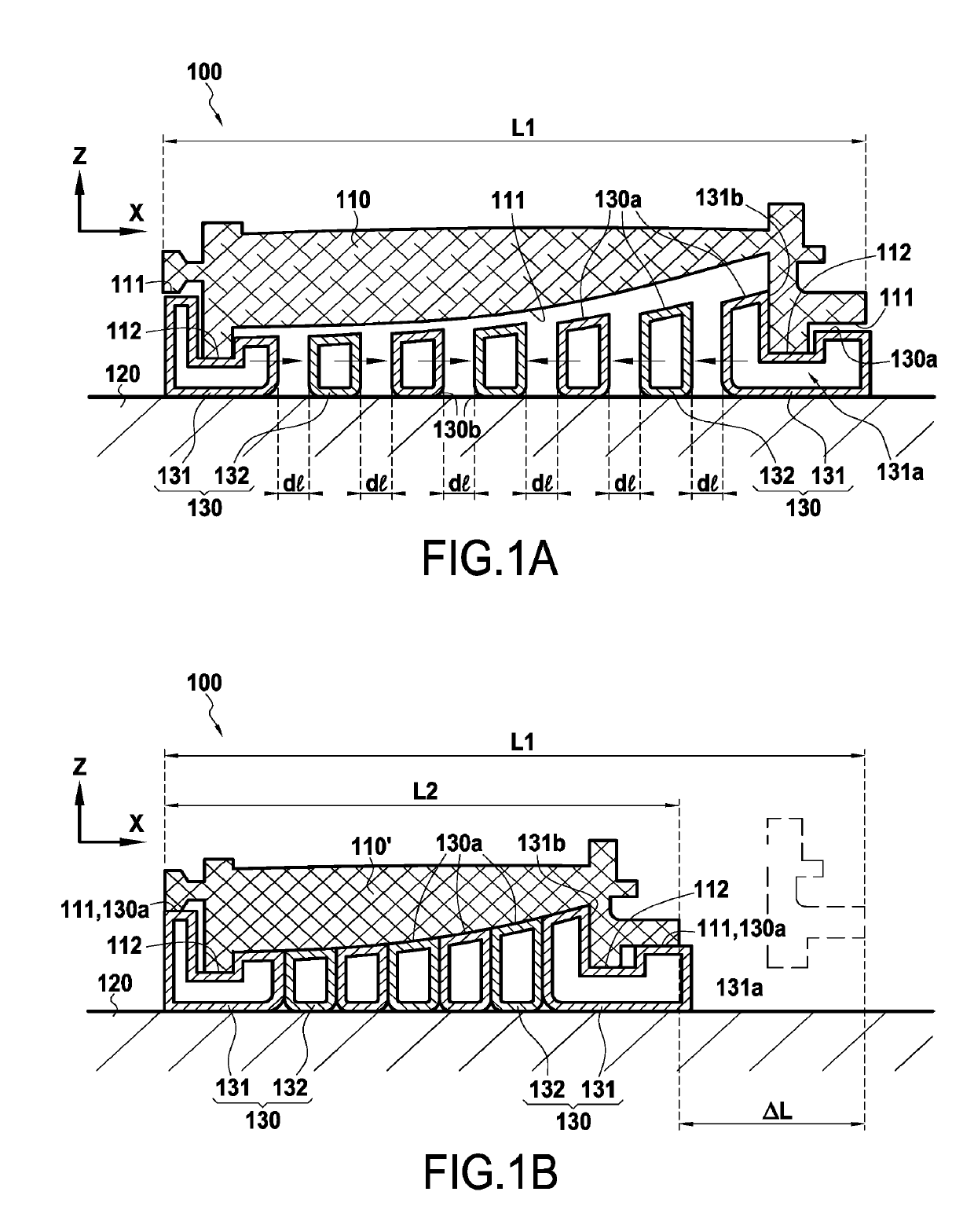
[0041]FIGS. 1A and 1B show tooling 100 of the invention in a substantially one-dimensional configuration. The arrangement of the tooling 100 shown in FIG. 1A is that adopted prior to the sintering step beginning, whereas the configuration of FIG. 1B is that obtained after sintering has been performed.

[0042]FIG. 1A shows tooling 100 of the invention for supporting a vane preform 110. Once it has been sintered (FIG. 1B), the vane 110′ may constitute a guide vane for an aviation turbine engine. In this example, the vane preform 110 has a plurality of suspended surfaces 111 that are suspended relative to two bearing surfaces 112 and presents a total length L1 in its longitudinal direction (along a horizontal axis X), the length L1 of the preform 110 being much greater than its width.

[0043]The vane preform 110 is previously made by a known technique of shaping powder. By way of example, mention may be made of the powder injection molding method that consists in preparing a composition co...

second embodiment

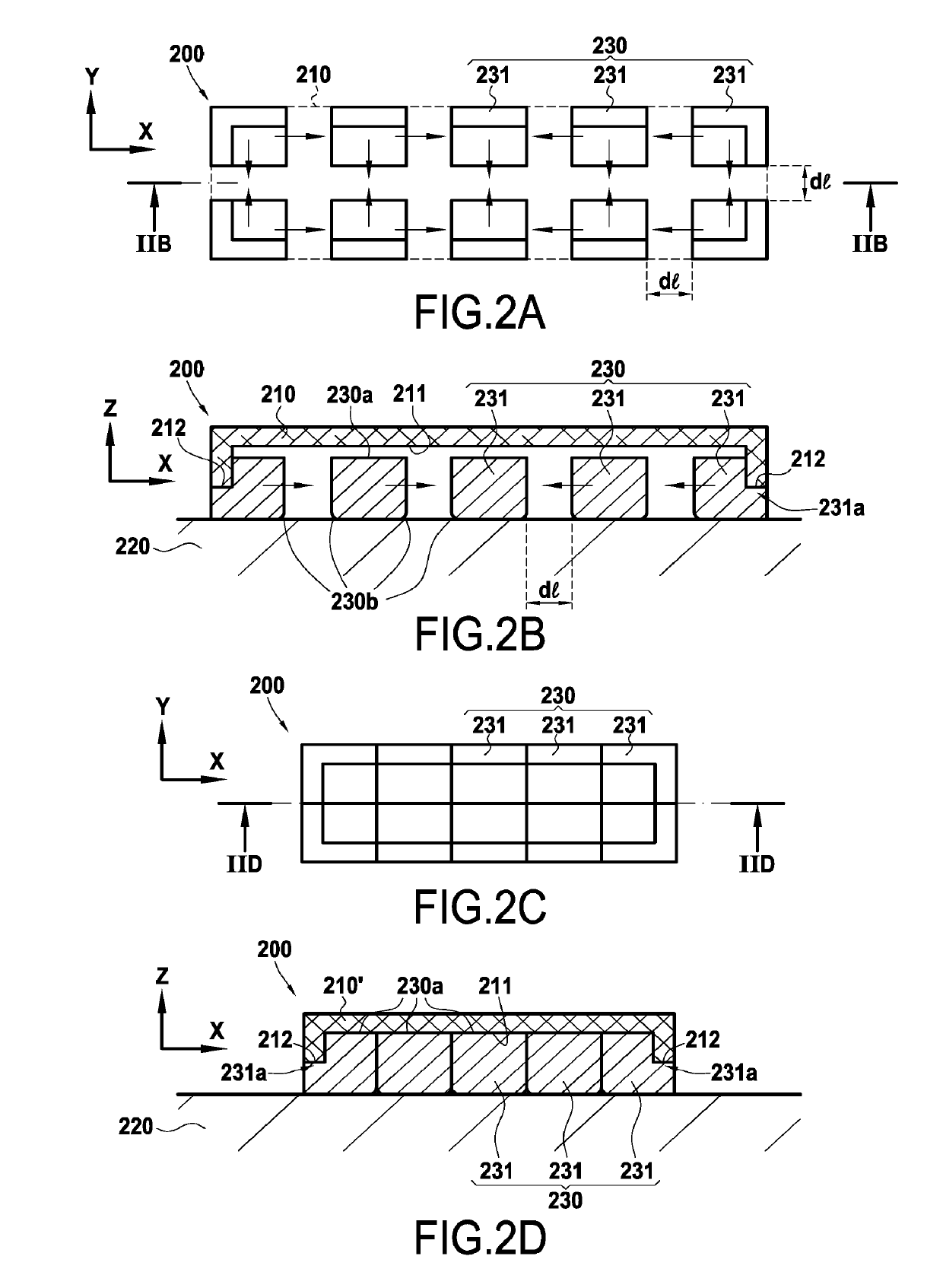
[0062]FIGS. 2A to 2D show tooling 200 of the invention in a two-dimensional configuration with a shape of rectangular type.

[0063]FIGS. 2A and 2B are respectively a plan view and a longitudinal section view on plane IIB of the tooling 200 before the sintering step. The tooling 200 is for supporting a preform 210 of rectangular shape that presents a suspended surface 211 extending longitudinally along an axis X and transversely along an axis Y. In accordance with the invention, the tooling 200 comprises a tray 220 surmounted by a set of blocks 230 made up in this example of two rows of outer blocks 231 that support the preform via its bearing surfaces 212, these surfaces 212 being in contact with steps 231a positioned in the blocks 231 (the steps 231a have the same function as the grooves 131a of the tooling 100).

[0064]With this shape, the preform needs to be held in the longitudinal and transverse directions in order to avoid suffering creep, which explains the use of the set of bloc...

third embodiment

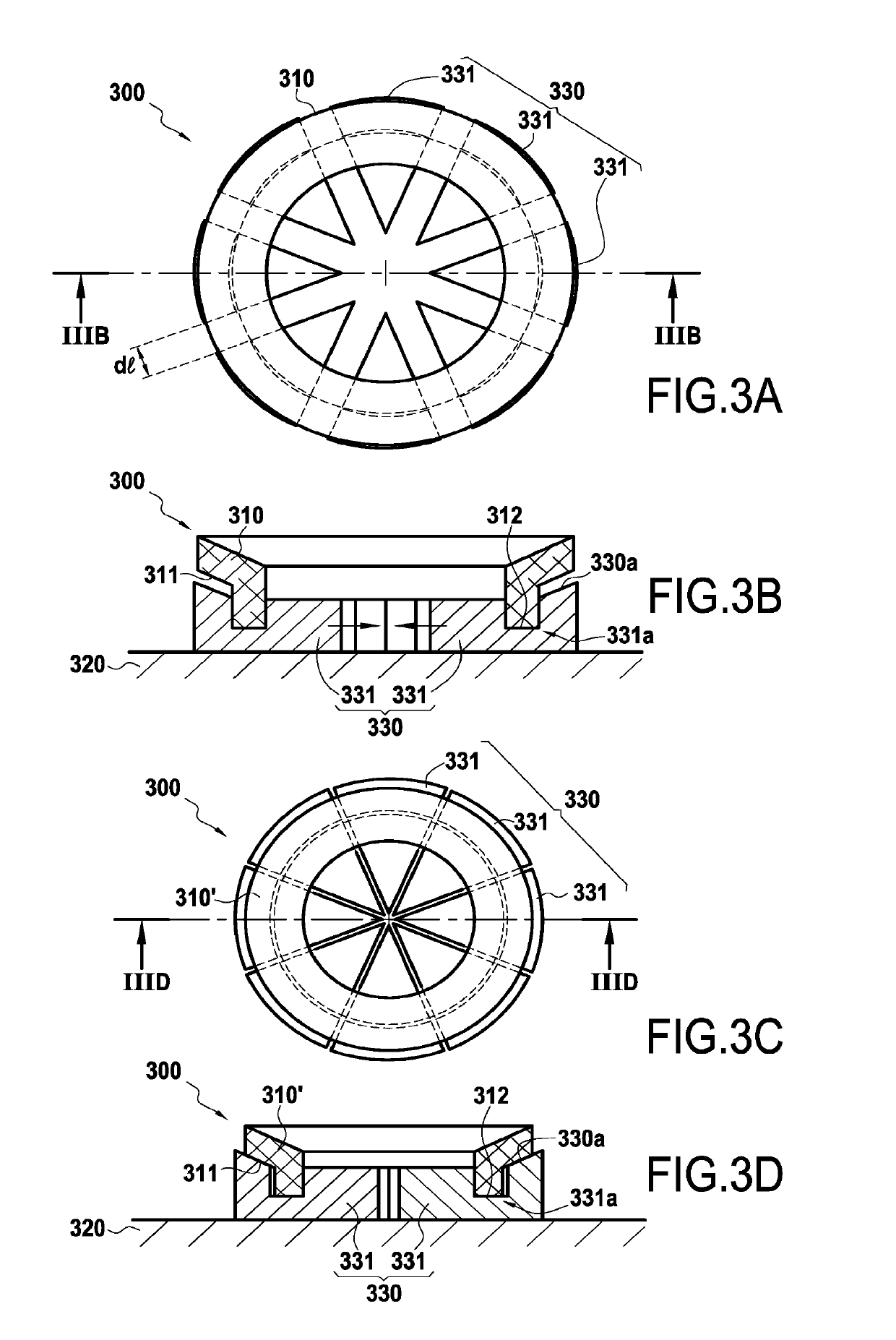
[0068]FIGS. 3A to 3D show tooling 300 of the invention in a two-dimensional configuration with a shape of cylindrical type (or indeed a body of revolution).

[0069]FIGS. 3A and 3B are respectively a plan view and a longitudinal section view on plane IIIB of the tooling 300 before the sintering step. The tooling 300 is to support a preform 310 in the form of a ring and presenting a cantilevered-out surface 311 at its periphery. In accordance with the invention, the tooling 300 comprises a tray 320 surmounted by a set of blocks 330 made up in this example of outer blocks 331 in the form of sectors supporting the preform via bearing surfaces 312 thereof, the bearing surfaces 312 being received in grooves 331a formed in the blocks 331.

[0070]In this example, the cantilevered-out surface 311 of the preform 310 slopes a little and is situated on the outside (relative to the center of the ring) of the bearing surface 312. Thus, the surfaces 330a of the blocks 331 for supporting the preform sl...


PUM

PropertyMeasurementUnit
shrinkageaaaaaaaaaa
angleaaaaaaaaaa
thicknessaaaaaaaaaa

Abstract

The invention provides tooling (100) for acting during heat treatment to support a preform (110) of a three-dimensional part obtained by shaping a metal or ceramic powder, the preform presenting at least one bearing surface (112) on which it can rest and at least one suspended surface (111) that is suspended relative to the bearing surface, the tooling comprising a tray (120), and a plurality of blocks (130) arranged on the tray and each having at least one surface (130a) for supporting the preform, the blocks being suitable for moving relative to one another by sliding on the tray between a first position in which the blocks are spaced apart from one another and together define a first volume, and a second position in which the blocks together define a second volume that is smaller than the first volume. The invention also provides a method of heat treating a preform made of powder and using such tooling.

Description

BACKGROUND OF THE INVENTION[0001]The present invention relates to the general field of applying heat treatment to preforms of parts that are made by shaping powders. The invention applies more particularly, but not exclusively, to sintering preforms of three-dimensional parts that are obtained by shaping metal or ceramic powder.[0002]It is nowadays common practice to use methods of fabricating three-dimensional parts out of metal (or metal alloy) or out of ceramic that involve a step of shaping a powder in order to obtain a preform (e.g. by using a powder or metal injection molding (PIM or MIM) technique with the help of a binder, e.g. an organic binder, or powder compaction molding), followed by a step of sintering the preform.[0003]During the step of sintering the preform (or of applying heat treatment at high temperature), several thermomechanical phenomena occur:[0004]the material expands thermally, depending on the coefficient of thermal expansion of the material constituting t...

Claims


Application Information

Patent Timeline
Patent Type & Authority Patents(United States)
IPC IPC(8): C04B37/00
CPCC04B37/001C04B37/005C04B2235/9615C04B2237/064C04B2237/066C04B2237/84C04B2237/341C04B2237/343C04B2237/348C04B2237/368C04B2237/34
Inventor FRIBOURG, GUILLAUME
Owner SN DETUDE & DE CONSTR DE MOTEURS DAVIATION S N E C M A
Why Eureka
Try Eureka