
In-ear bluetooth headset

a bluetooth headset and headset body technology, applied in the field of bluetooth ® headsets, can solve the problems of increasing the difficulty of antenna design, poor antenna performance, and increasing the difficulty of antenna performance, and achieve the effects of reducing cost, saving space, and high antenna radiation efficiency

Active Publication Date: 2019-03-26
SHENZHEN ATX TECH CO LTD
View PDF3 Cites 4 Cited by
  • Summary
  • Abstract
  • Description
  • Claims
  • Application Information

AI Technical Summary

Benefits of technology

[0006]In order to solve above technical problem, the present invention provides an in-ear BLUETOOTH® headset, which does not require an independent antenna, saves space, has lower cost, has high radiation efficiency of the antenna and is conducive to widespread application.
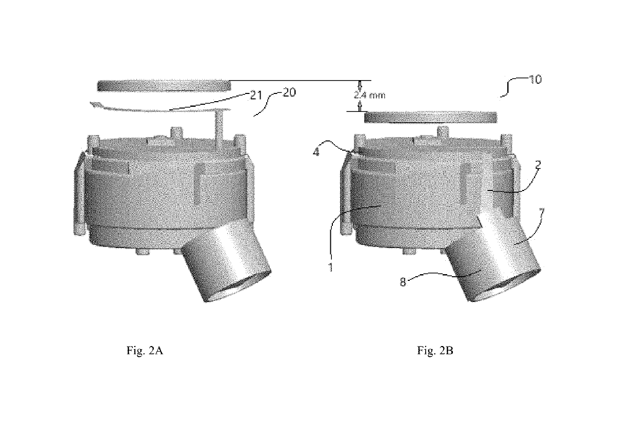
[0008]The antenna of the in-ear BLUETOOTH® headset works on the BLUETOOTH® 2.4 GHz frequency band, having a wide frequency band and high radiation efficiency.
[0009]Compared with the prior art, the in-ear BLUETOOTH® headset implementing the present invention has the following advantages:

Problems solved by technology

The reduction in size and the addition of metal housing will inevitably increase the difficulty of antenna design.
If the existing antenna designs, such as monopole antennas, IFA antennas, and loop antennas, are still used, the antenna performance may not meet the requirements and due to the strong vibration during exercise, the existing antenna design structure is not rigid and it is easily subject to vibrations and is deformed or even broken resulting in poor antenna performance.
Although its versatility is good, a certain clearance area is required to occupy a certain space in the headset, the cost is high, and the radiation efficiency of the antenna is low, which is not suitable for application on the in-ear BLUETOOTH® headset.

Method used


Image

  • In-ear bluetooth headset
  • In-ear bluetooth headset

Examples


Embodiment Construction

[0018]The embodiments of technical solution of the present invention will be described in detail in connection with the attached drawings. The following embodiments only serve as examples to illustrate the technical solution of the invention and not be given to limit the scope of protection of the invention.

[0019]It shall be noted that unless otherwise mentioned, all technical and scientific terms used herein have the same meaning as commonly understood by a person skilled in the art to which the utility model belong.

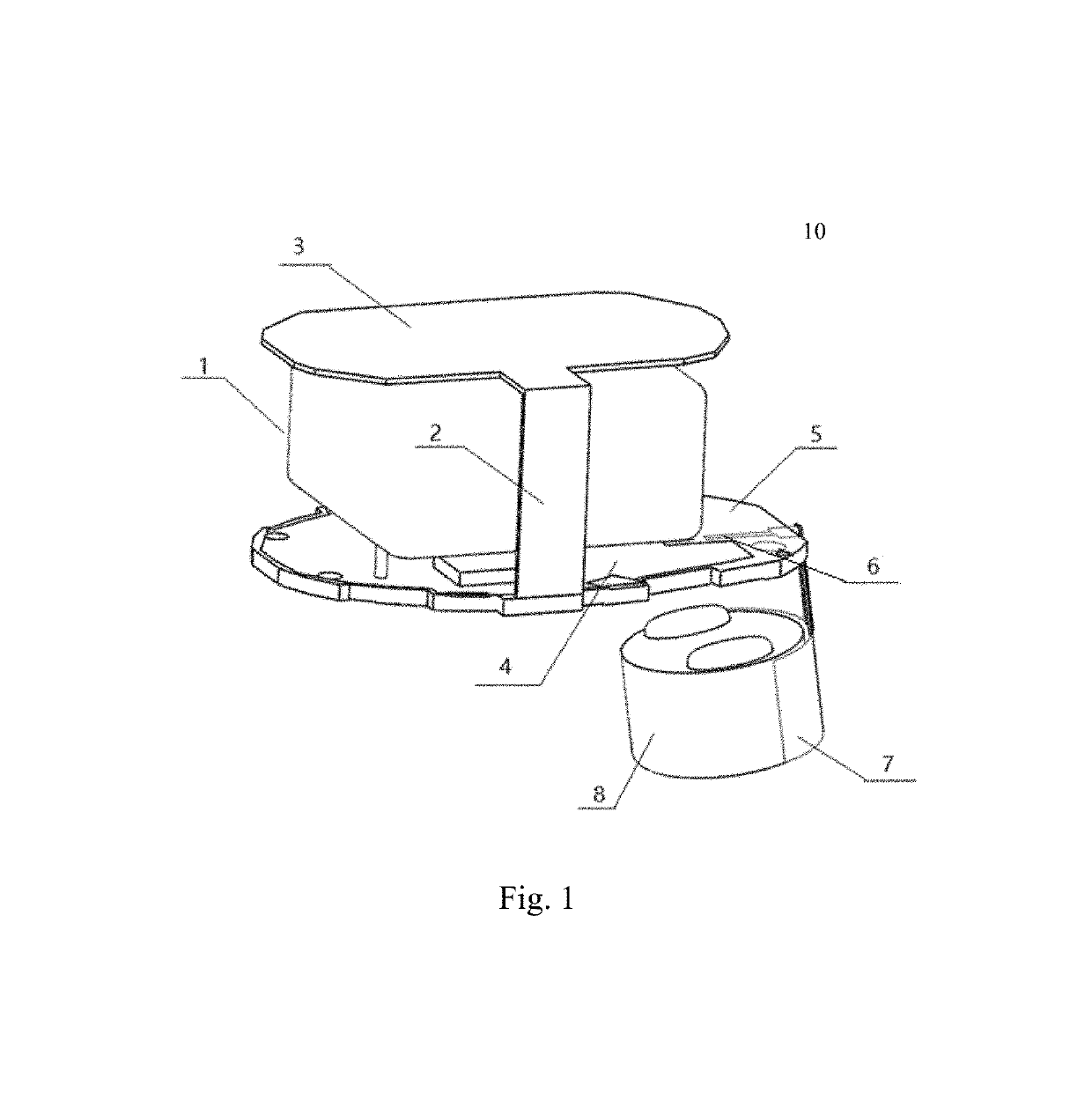
[0020]According to one embodiment of the in-ear BLUETOOTH® headset, with reference to FIG. 1, the headset 10 comprises a housing (not shown), a battery 1, a main printed circuit board (PCB) 5, a headset control button printed circuit board 3, a speaker 8 and an antenna; the other parts are operatively connected to each other except for a housing that covers other parts. The main printed circuit board 5 includes a first surface and a second surface. In one embodiment, th...


PUM


Abstract

An in-ear BLUETOOTH® headset antenna for single-ear and double-ear BLUETOOTH® headset. The antenna includes a radiation unit and a ground unit, both utilizing components that make up the headset. The radiation unit is composed of a horn of the BLUETOOTH® headset and a conductive foil attached to the horn surface. One end of the conductive foil is attached to the surface of the headset horn and the other end is connected to the feed point of the RF circuit antenna of the BLUETOOTH® headset. The ground unit includes copper pouring on a main printed circuit board connected to copper pouring a key printed circuit board by a cable. No additional antennas are required, and the in-ear BLUETOOTH® headset antenna reduces costs, saves space, and improves the radiation efficiency of the antenna due to the increased effective radiation area of the antenna.

Description

RELATED APPLICATIONS[0001]The present application is a continuation of the international application PCT / CN2017 / 081522 filed Apr. 21, 2017, which claims the benefit of CN201621083827.4 filed Sep. 27, 2016, each of which is incorporated herein by reference in its entirety.FIELD OF THE INVENTION[0002]The present invention relates to the technical field of BLUETOOTH® headset, in particular, to an in-ear BLUETOOTH® headset, which can be applied to the single-ear and double-ear BLUETOOTH® headset.BACKGROUND OF THE INVENTION[0003]Since the BLUETOOTH® headset is portable, people are happy to use it in various occasions, in particular, when they are in sports, they can listen to music and receive calls through BLUETOOTH® headsets, thus bringing great convenience to people in the sports process. So the requirements for the performance and appearance of BLUETOOTH® headsets are increasing. In order to increase the competitiveness of products, manufacturers have introduced BLUETOOTH® headsets o...

Claims


Application Information

Patent Timeline
Patent Type & Authority Patents(United States)
IPC IPC(8): H04R1/10H01Q1/38H01Q9/42H01Q1/27H01Q1/48H01Q1/44
CPCH04R1/1041H01Q1/273H01Q1/38H01Q9/42H04R1/1016H04R2420/07H01Q1/44H01Q1/48H04R2225/51
Inventor XU, MINGQIANGHUANG, YUECHUN
Owner SHENZHEN ATX TECH CO LTD
Learn More