Micro light-emitting-diode display panel and manufacturing method thereof

a technology of light-emitting diodes and display panels, which is applied in the direction of basic electric elements, electrical apparatus, and semiconductor devices, can solve the problems of complex bonding process, less reliable, and difficult, and achieve the effects of reducing the difficulty of electrode bonding, improving the reliability of electrode bonding, and facilitating connection

Active Publication Date: 2019-04-16
TCL CHINA STAR OPTOELECTRONICS TECH CO LTD
View PDF12 Cites 3 Cited by
  • Summary
  • Abstract
  • Description
  • Claims
  • Application Information

AI Technical Summary

Benefits of technology

[0006]An object of the present invention is to provide a micro light-emitting-diode display panel, which can reduce the bonding difficulty of the light-emitting-diodes and improve the reliability of the electrode bonding of the light-emitting-diodes.
[0007]An object of the present invention is to further provide a manufacturing for a micro light-emitting-diode display panel, which can reduce the bonding difficulty of the light-emitting-diodes and improve the reliability of the electrode bonding of the light-emitting-diodes.
[0054]The beneficial effects of the present invention is: the present invention provides a micro light-emitting-diode display panel which presses and fixes the micro light-emitting-diodes into a resin adhesive layer by filling the resin adhesive layer in the pixel groove. Meanwhile, the electrode at the bottom of the micro light-emitting-diode is guided to the top of the micro light-emitting-diode by the connection electrode, making the two electrodes of the micro light-emitting-diode are at the top, to facilitate the connection between the electrodes of the micro light-emitting-diode and the electrode points, which can reduce the difficulty of the electrode bonding of the micro light-emitting-diode, and improve the reliability of the electrode bonding of the micro light-emitting-diode. The invention also provides a method for manufacturing a micro light-emitting-diode display panel, which can reduce the difficulty of the electrode bonding of the micro light-emitting-diode, and improve the reliability of the electrode bonding of the micro light-emitting-diode.

Problems solved by technology

The bonding process is complex, difficult, and less reliable.

Method used


Image

  • Micro light-emitting-diode display panel and manufacturing method thereof
  • Micro light-emitting-diode display panel and manufacturing method thereof
  • Micro light-emitting-diode display panel and manufacturing method thereof

Examples


Embodiment Construction

[0066]The technical proposals and the effects of the present invention will be described in further detail with reference to the below preferred embodiments of the present invention and their accompanying drawings.

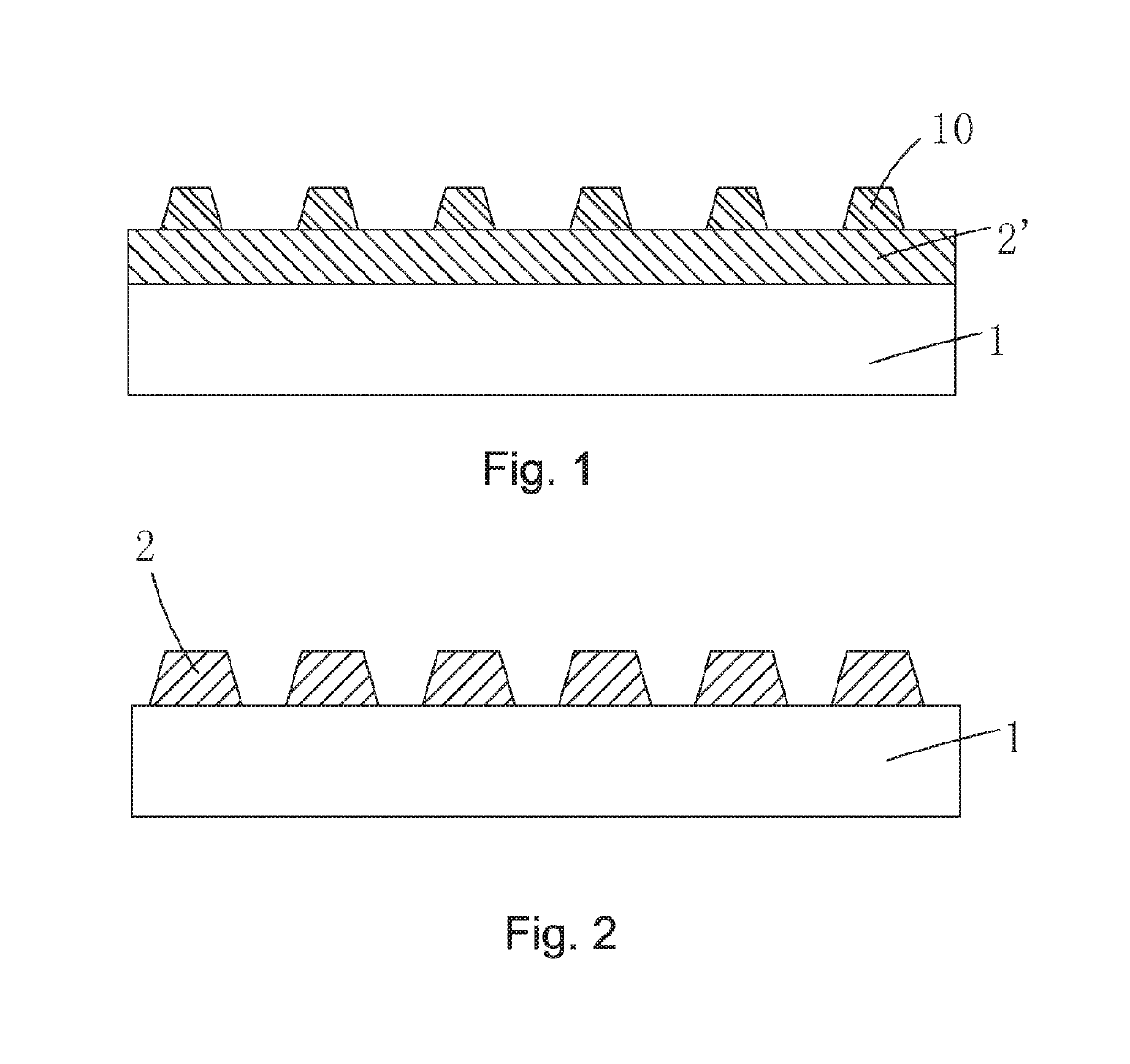
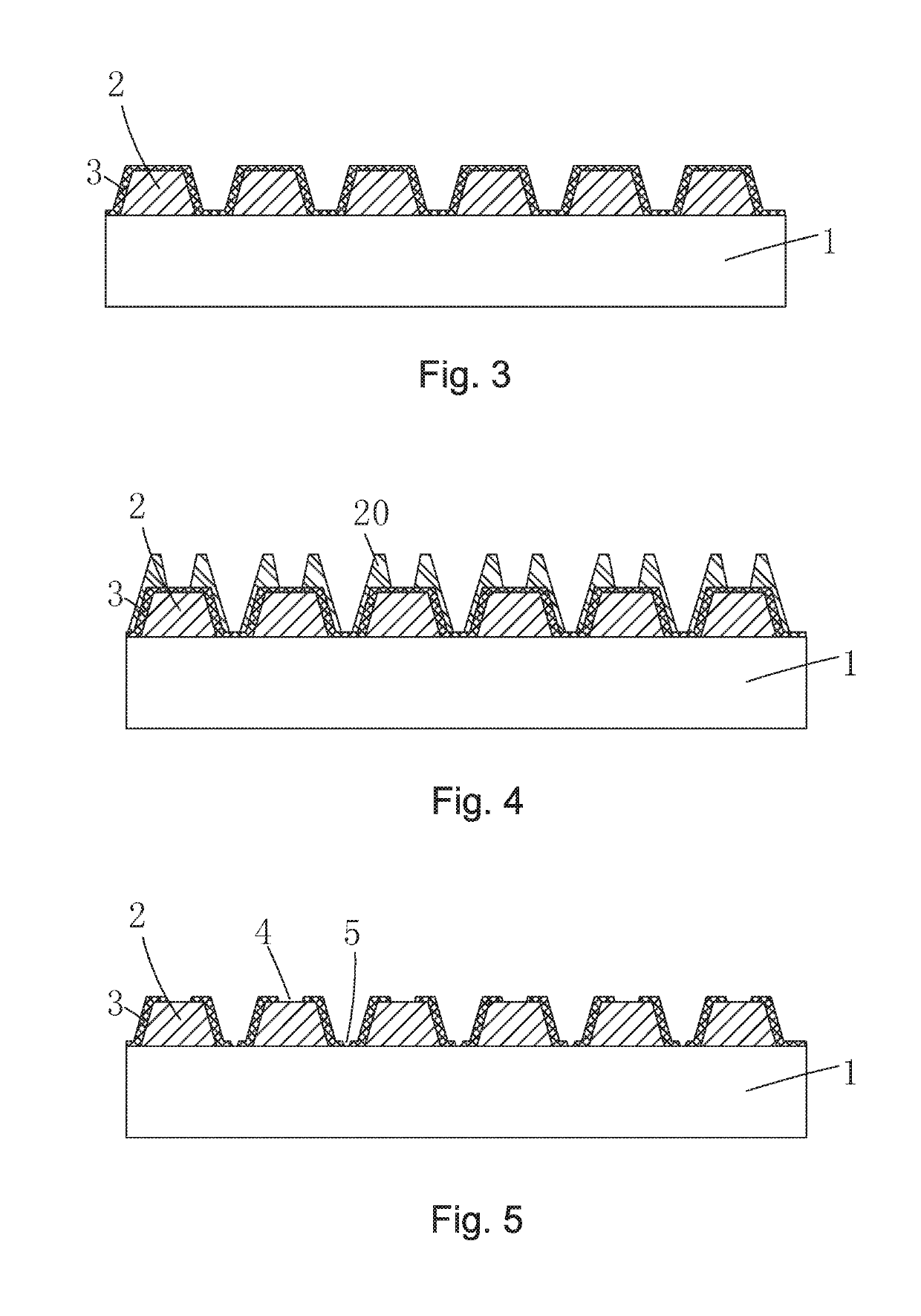
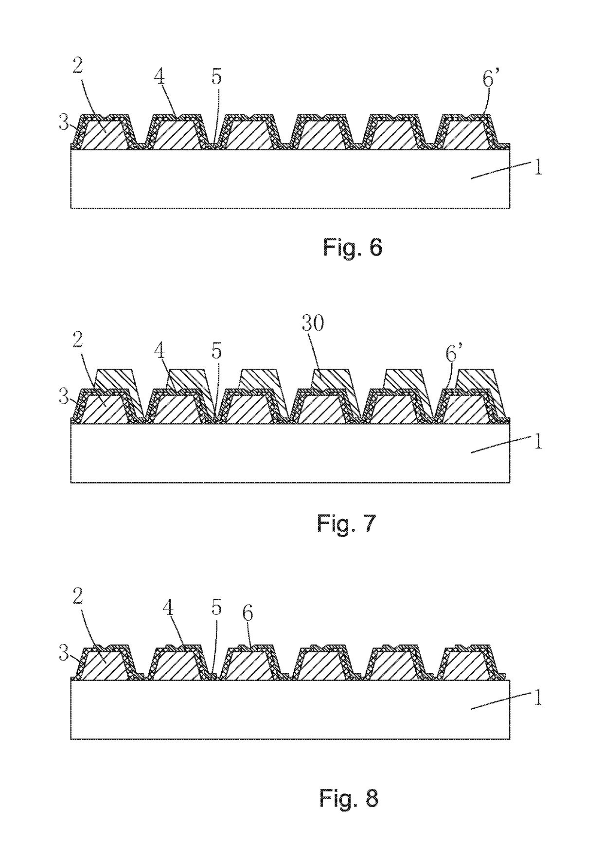
[0067]Please refer to FIG. 16, the present invention provides a micro light-emitting-diode display panel, which comprises a base substrate 41, a pixel definition layer 45 disposed on the base substrate 41, a pixel groove 15 formed in the pixel definition layer 45, a resin adhesive layer 13 disposed in the pixel groove 15, a micro light-emitting-diode 200 embedded in the resin adhesive layer 13, and a first electrode point 43 and a second electrode point 44 on the pixel definition layer 45 respectively located on both sides of the pixel groove 15.

[0068]The micro light-emitting-diode 200 comprises: a connection electrode 6, an LED semi-conductor layer 2 disposing above the connection electrode 6 and contacting with the connection electrode 6, a first electrode 71 disposing o...


PUM


Abstract

The present invention provides a micro light-emitting-diode display panel and a manufacturing method thereof. The micro light-emitting-diode display panel which presses and fixes the micro light-emitting-diodes into a resin adhesive layer by filling the resin adhesive layer in the pixel groove. Meanwhile, the electrode at the bottom of the micro light-emitting-diode is guided to the top of the micro light-emitting-diode by the connection electrode, making the two electrodes of the micro light-emitting-diode are at the top, to facilitate the connection between the electrodes of the micro light-emitting-diode and the electrode points, which can reduce the difficulty of the electrode bonding of the micro light-emitting-diode, and improve the reliability of the electrode bonding of the micro light-emitting-diode.

Description

BACKGROUND OF THE INVENTIONField of Invention[0001]The present invention relates to the field of liquid crystal display, and more particularly to a micro light-emitting-diode display panel and a manufacturing method thereof.Description of Prior Art[0002]Because of the advantages of high quality, power saving, thin body and wide applications, the flat panel display devices has become a mainstream in the display devices and been widely used in various consumer electronic devices, such as mobile phones, personal digital assistants, digital cameras, laptops, and desktop computers.[0003]A micro LED display is a display that achieves image display by using a high density and small size LED arrays integrated on a substrate as display pixels, the same as the large-size outdoor LED display, each pixel can be addressed, be individually driven to light, can be seen as a shrink-down version of the outdoor LED display, to reduce the pixel distance from millimeter to micron. The Micro LED display...

Claims


Application Information

Patent Timeline
Patent Type & Authority Patents(United States)
IPC IPC(8): H01L33/00H01L33/10H01L25/16H01L33/30H01L33/60H01L33/20H01L33/52H01L27/15H01L33/48
CPCH01L33/005H01L25/167H01L27/15H01L33/10H01L33/60H01L33/30H01L33/486H01L33/52H01L33/20H01L27/156H01L33/0095H01L33/38H01L25/0753H01L33/62H01L33/36H01L33/44H01L33/56H01L27/153H01L33/0093
Inventor LU, MACAI
Owner TCL CHINA STAR OPTOELECTRONICS TECH CO LTD
Why Eureka
Try Eureka