Method of manufacturing piezoelectric vibrator element, piezoelectric vibrator element, and piezoelectric vibrator

a technology of piezoelectric vibrator and piezoelectric vibrator, which is applied in the manufacture/assembly of piezoelectric/electrostrictive devices, electric devices, and impedence networks. it can solve the problems of difficult laser beam trimming and frequency adjustment by trimming, and achieve superior vibration characteristics, high quality, and superior vibration characteristics.

Active Publication Date: 2019-04-16
SII CRYSTAL TECH
View PDF14 Cites 1 Cited by
  • Summary
  • Abstract
  • Description
  • Claims
  • Application Information

AI Technical Summary

Benefits of technology

[0010]The present invention has been made in consideration of the circumstances described above, and has an object of providing a method of manufacturing a piezoelectric vibrator element, a piezoelectric vibrator element, and a piezoelectric vibrator, which are high in quality, superior in vibration characteristics, and capable of suppressing the variation in frequency after the frequency adjustment.

Problems solved by technology

However, if the trimming is performed using a laser beam as in Patent Document 1 described above, there is a possibility that a burr is formed in a recessed part of the weight metal film formed by the trimming, or particles of the weight metal film scattered by the trimming adhere again to the surfaces of the vibrating arm parts.
Further, if the burr or the particle is separated after the fine adjustment, there arises a problem that the frequency adjusted by the trimming varies.
In contrast, if the thickness of the weight metal film is increased in order to reduce the variation in frequency, the trimming by the laser beam becomes difficult.

Method used


Image

  • Method of manufacturing piezoelectric vibrator element, piezoelectric vibrator element, and piezoelectric vibrator
  • Method of manufacturing piezoelectric vibrator element, piezoelectric vibrator element, and piezoelectric vibrator
  • Method of manufacturing piezoelectric vibrator element, piezoelectric vibrator element, and piezoelectric vibrator

Examples


Embodiment Construction

[0037]An embodiment according to the invention will hereinafter be described with reference to the accompanying drawings.

[0038]

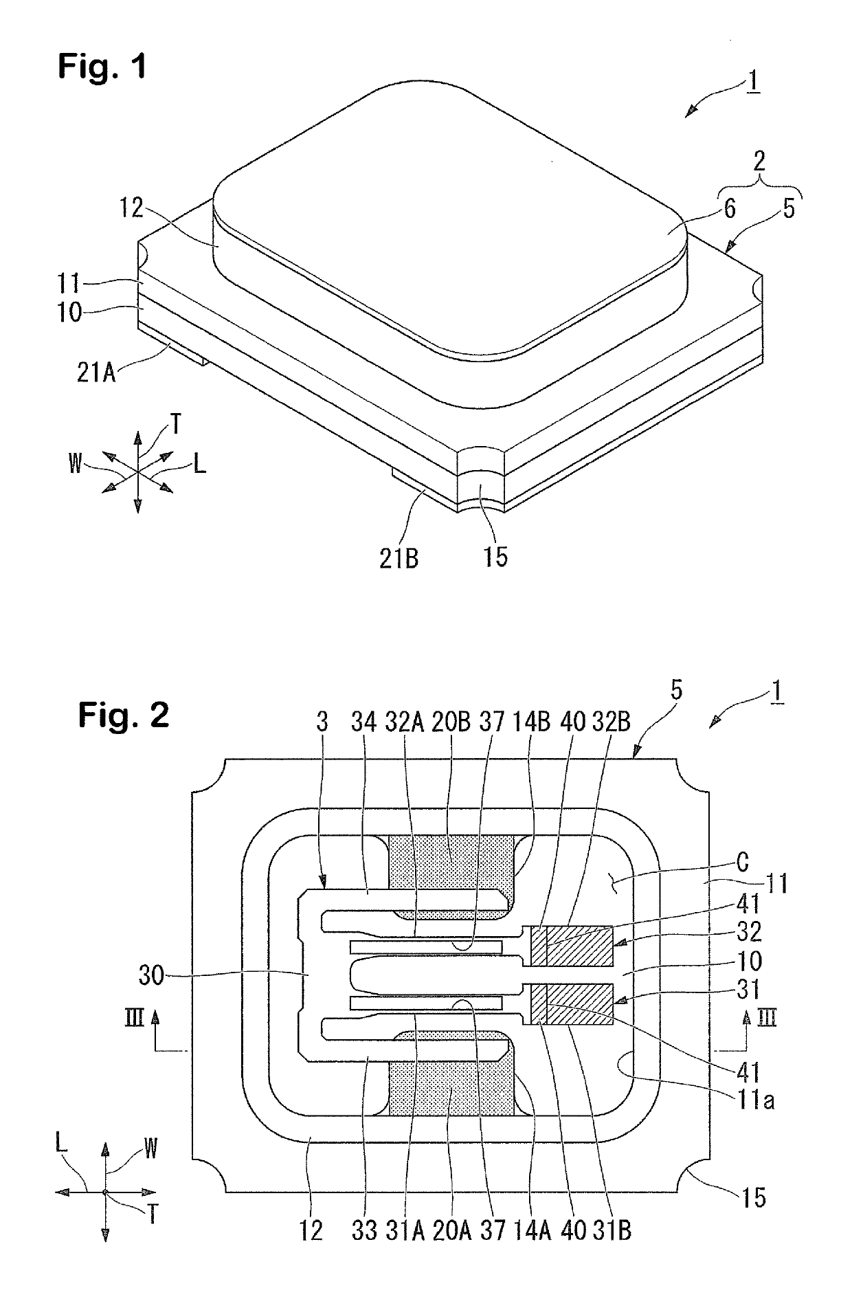
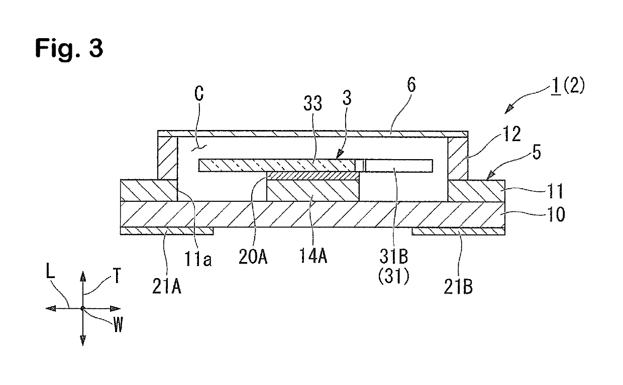
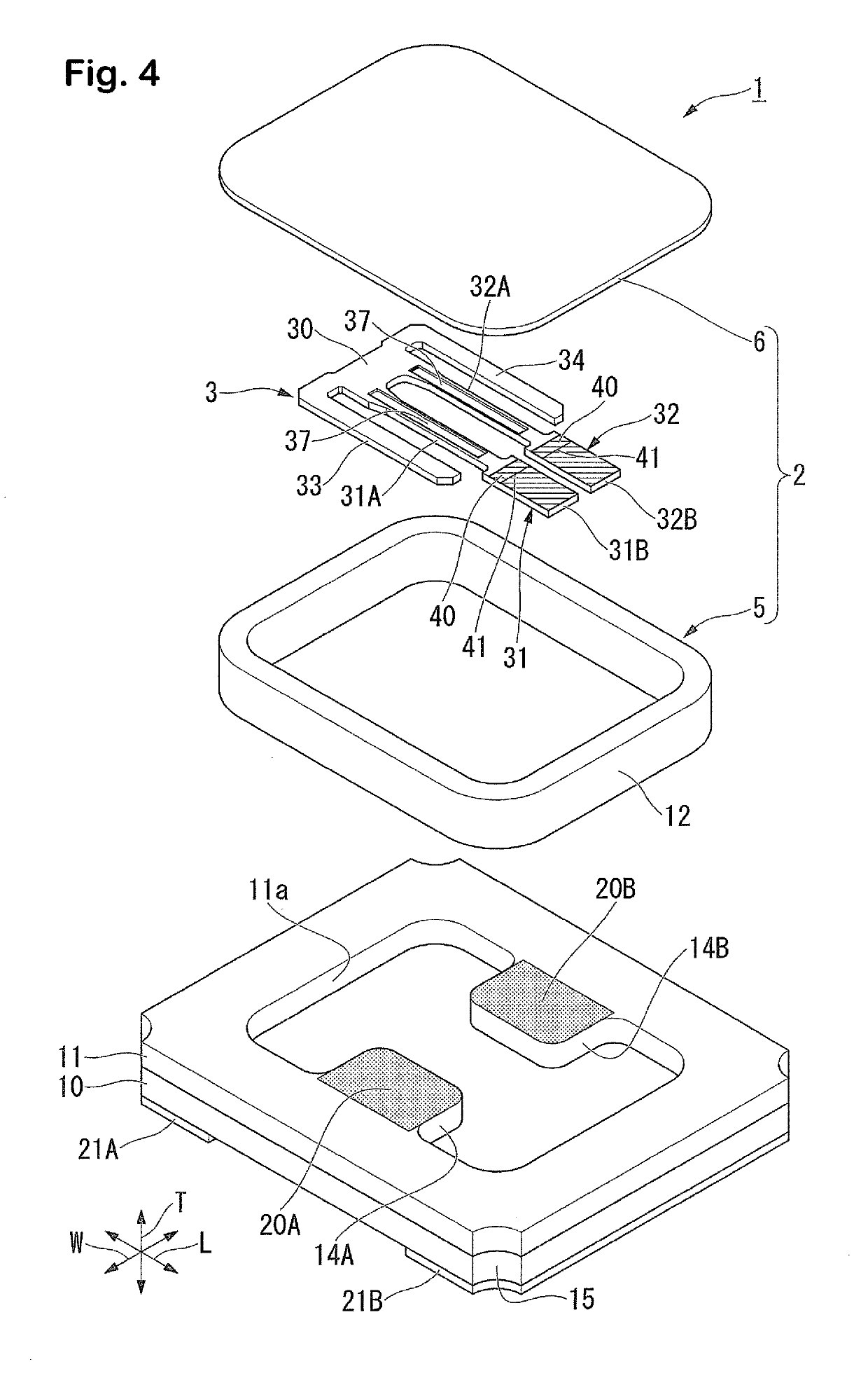
[0039]FIG. 1 is an external perspective view of a piezoelectric vibrator 1 according to the embodiment of the invention. FIG. 2 is a plan view of the piezoelectric vibrator 1, showing a state with a sealing plate 6 detached. FIG. 3 is a cross-sectional view along the line III-III shown in FIG. 2. FIG. 4 is an exploded perspective view of the piezoelectric vibrator 1 according to the embodiment.

[0040]As shown in FIG. 1 through FIG. 4, the piezoelectric vibrator 1 is a so-called ceramic package-type surface-mounted vibrator, and is provided with a package 2 incorporating a cavity C hermetically sealed, and a piezoelectric vibrator element 3 housed in the cavity C. It should be noted that the piezoelectric vibrator 1 exhibits a rectangular solid shape. Therefore, in the present embodiment, the longitudinal direction of the piezoelectric vibrator 1 is referred t...


PUM


Abstract

A method of manufacturing a piezoelectric vibrator element, a piezoelectric vibrator element, and a piezoelectric vibrator, superior in vibration characteristics, high in quality, and capable of suppressing a variation in frequency after a frequency adjustment, are provided. The method includes a first frequency adjustment step of performing ion milling on a weight metal film for a frequency adjustment formed on a surface of a tip part in each of a pair of vibrating arm parts, and a second frequency adjustment step of performing ion milling on the weight metal film at a lower etch rate than in the first frequency adjustment step after the first frequency adjustment step.

Description

RELATED APPLICATIONS[0001]This application claims priority under 35 U.S.C. § 119 to Japanese Patent Application No. 2015-104990 filed on May 22, 2015, the entire content of which is hereby incorporated by reference.BACKGROUND OF THE INVENTION[0002]1. Field of the Invention[0003]The present invention relates to a method of manufacturing a piezoelectric vibrator element, a piezoelectric vibrator element, and a piezoelectric vibrator.[0004]2. Background Art[0005]For example, in the electronic apparatus such as a cellular phone or a portable information terminal, there is used a piezoelectric vibrator using a quartz crystal or the like as a device used for a time source, a timing source for a control signal and so on, a reference signal source, and so on. As a piezoelectric vibrator of this kind, there has been known a device having a piezoelectric vibrator element hermetically encapsulated in a package provided with a cavity.[0006]The piezoelectric vibrator element described above is p...

Claims


Application Information

Patent Timeline
Patent Type & Authority Patents(United States)
IPC IPC(8): H01L41/22H03H9/02H03H9/205H03H3/04H03H9/21
CPCH03H3/04H03H9/21H03H2003/0428H03H3/02H03H9/02H03H9/02244H03H2003/023H10N30/01H10N30/05
Inventor KOBAYASHI, TAKASHI
Owner SII CRYSTAL TECH
Why Eureka
Try Eureka