Oscillation device and timepiece with temperature compensation function
a technology of oscillator and timepiece, which is applied in the direction of oscillator generator, horology, instruments, etc., can solve the problems of significant difference in flowability of current, affecting the accuracy of oscillator, and the inability to use metal materials for the dial of the clock in order, so as to improve the satisfaction level of users and improve accuracy. , the effect of superior textur
- Summary
- Abstract
- Description
- Claims
- Application Information
AI Technical Summary
Benefits of technology
Problems solved by technology
Method used
Image
Examples
first embodiment
Advantages of First Embodiment
[0071]According to the first embodiment described above, the following advantages can be obtained.
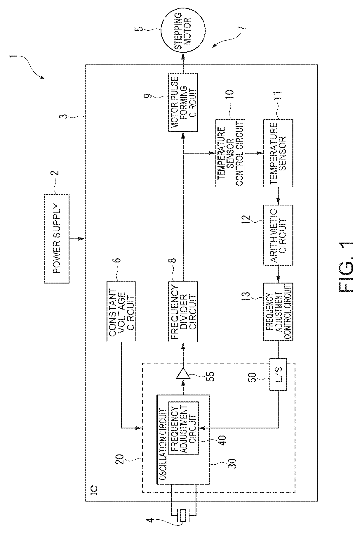
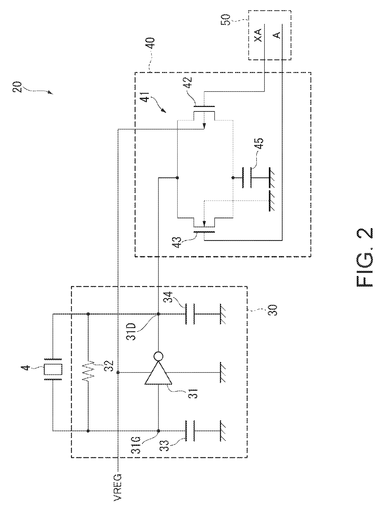
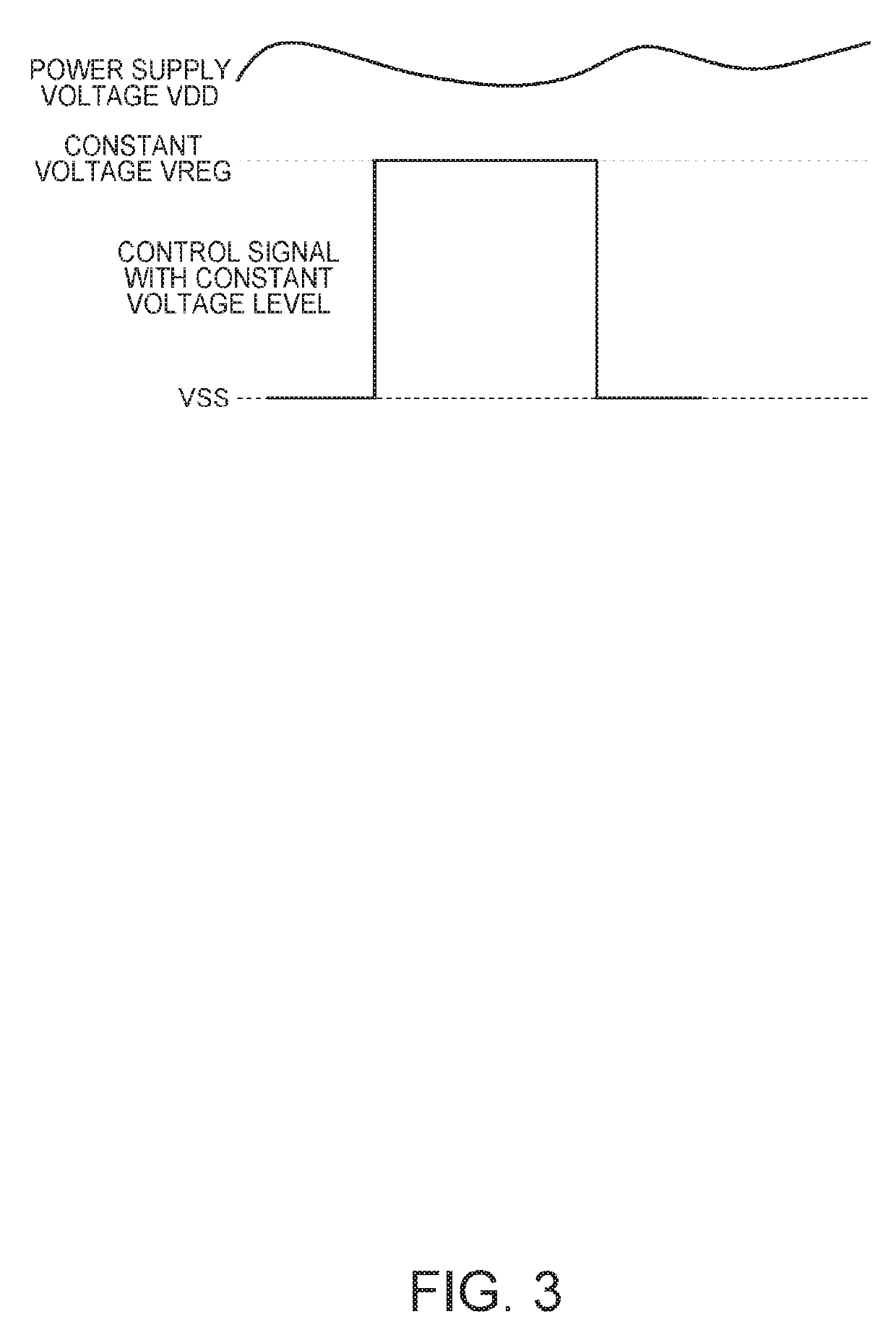
[0072]1. Since the constant voltage is applied to the gate and the substrate of the field-effect transistors 42, 43 having the connection relationship with the gate 31G or the drain 31D of the oscillation inverter 31 to drive the field-effect transistors 42, 43, even if the power supply voltage fluctuates, the fluctuation in the oscillation frequency of the oscillation circuit 30 can be suppressed, and thus, the oscillation signal with a constant frequency can be output.
[0073]2. According to the present embodiment, since the oscillation frequency does not fluctuate if the power supply voltage fluctuates, the correction amount due to the temperature becomes correct without being affected by the power supply voltage. Therefore, the timepiece with temperature compensation function 1 can keep the high accuracy until the terminal stage of discharge of the batter...
second embodiment
Advantages of Second Embodiment
[0079]In the oscillation device 20A according to the second embodiment, the field-effect transistors 321, 322 are provided as the feedback resistors in the oscillation circuit 30A, the constant voltage VREG and the constant voltage VSS are applied to the gates thereof, and the constant voltage VSS and the constant voltage VREG are applied to the substrate thereof. Therefore, even if the power supply voltage VDD fluctuates, the threshold voltage Vth does not fluctuate, and the ON resistance does not also fluctuate, and therefore, it is possible to prevent the feedback resistance value from changing. Therefore, even if the power supply voltage fluctuates, there is no chance for the power of the oscillation circuit 30A to change, and therefore, it is also possible to prevent the oscillation frequency of the oscillation circuit 30A from changing.
[0080]Further, since the field-effect transistors 321, 322 are used as the feedback resistors, the circuit scale...
modified examples
[0081]It should be noted that the invention is not limited to the embodiments described above, but includes other configurations capable of achieving the advantages of the invention. Such modified examples as described below are also included in the invention.
[0082]For example, although in each of the embodiments described above, there is described the case in which the constant voltage VSS is defined as the ground, the same advantages can also be obtained even in the case in which the constant voltage VDD is defined as the ground. For example, in the configuration of the first embodiment, in order to define the constant voltage VDD as the ground, it is sufficient to adopt the circuit shown in FIG. 7. It should be noted that although not shown in the drawings, the constant voltage VDD can be defined as the ground also in the second embodiment.
[0083]Further, the relationship between the constant voltage VREG output by the constant voltage circuit 6 and the temperature is set to have ...
PUM
 Abstract
Description
Claims
Application Information
 - R&D
- Intellectual Property
- Life Sciences
- Materials
- Tech Scout
- Unparalleled Data Quality
- Higher Quality Content
- 60% Fewer Hallucinations
Browse by: Latest US Patents, China's latest patents, Technical Efficacy Thesaurus, Application Domain, Technology Topic, Popular Technical Reports.
© 2025 PatSnap. All rights reserved.Legal|Privacy policy|Modern Slavery Act Transparency Statement|Sitemap|About US| Contact US: help@patsnap.com


