Inkjet printing apparatus and control method
a technology of inkjet printing and control method, applied in the field of inkjet printing apparatus, can solve the problems of defective ejection, inability to complete the recovery of ejection state, and easy ejection of defective ink, so as to prevent defective ejection and wasteful ink consumption.
- Summary
- Abstract
- Description
- Claims
- Application Information
AI Technical Summary
Benefits of technology
Problems solved by technology
Method used
Image
Examples
first embodiment
(First Embodiment)
(Description of Inkjet Printing Apparatus)
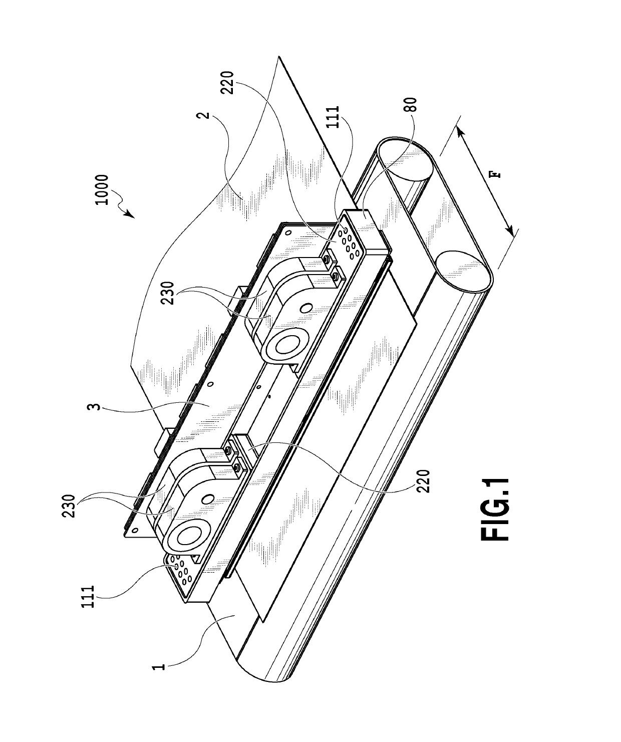
[0050]FIG. 1 is a view illustrating outline constitution of a liquid ejecting device for ejecting a liquid of the present invention or particularly an inkjet printing apparatus (hereinafter, also referred to as a printing apparatus) 1000 which performs printing by ejecting ink. The printing apparatus 1000 is a line-type printing apparatus including a conveyance unit 1 which conveys a printing medium 2, and a line-type print head (liquid ejection head) 3 arranged substantially orthogonally to a conveyance direction of the printing medium 2, in which continuous printing is performed in a single pass while continuously or intermittently conveying a plurality of printing mediums 2. The print head 3 includes a negative pressure control unit 230 which controls a pressure (negative pressure) in a path, a liquid supply unit 220 having fluid communication with the negative pressure control unit 230, a liquid connection portion 111 w...
second embodiment
(Second Embodiment)
[0140]Hereinafter, a second embodiment of the present invention will be described by referring to the attached drawings. Since basic constitutions of this embodiment are similar to the first embodiment, only featured constitutions will be described below.
[0141]FIG. 25 is a schematic view illustrating a circulation path applied to the printing apparatus 1000 of this embodiment. In the circulation path of this embodiment, a tank used as the main tank in the first embodiment is changed to a buffer tank 1003, and a supply path is provided from a main tank 1006 to the buffer tank 1003 through a valve 1005. In a state where valves 1011 and 1012 are both closed, while a valve 1010 is opened, a pump 1001 connected to the buffer tank reduces a pressure in the buffer tank and brings the valve 1005 into an open state, the ink is supplied from the main tank to the buffer tank by a negative pressure generated in the buffer tank. On the other hand, as in FIG. 26, time other tha...
third embodiment
(Third Embodiment)
[0150]Hereinafter, a third embodiment of the present invention will be described by referring to the attached drawings. Since basic constitutions of this embodiment are similar to the second embodiment, only featured constitutions will be described below.
[0151]In the third embodiment, evaporation from the main tank is also considered, which is a different point. Independently of the evaporation amount and the consumed ink amount in the circulation path, an evaporation amount Vtank from the main tank is calculated.
[0152]The ink amount Jtank in the main tank is updated by subtraction on the basis of the consumed ink amount In and the evaporation amount V at each supply timing from the main tank to the buffer tank. On the other hand, the evaporation amount Vtank from the main tank is also updated at each timing that the ink supply operation is performed. The evaporation amount calculation processing from the main tank will be described by using a flowchart in FIG. 28....
PUM
 Abstract
Description
Claims
Application Information
 - R&D
- Intellectual Property
- Life Sciences
- Materials
- Tech Scout
- Unparalleled Data Quality
- Higher Quality Content
- 60% Fewer Hallucinations
Browse by: Latest US Patents, China's latest patents, Technical Efficacy Thesaurus, Application Domain, Technology Topic, Popular Technical Reports.
© 2025 PatSnap. All rights reserved.Legal|Privacy policy|Modern Slavery Act Transparency Statement|Sitemap|About US| Contact US: help@patsnap.com


