Building construction method

a construction method and building technology, applied in the field of building construction methods, can solve problems such as gaps or spaces between studs and wall panels, and achieve the effect of easy and thorough application

Active Publication Date: 2019-04-23
LEPAGE ROBERT
View PDF18 Cites 3 Cited by
  • Summary
  • Abstract
  • Description
  • Claims
  • Application Information

AI Technical Summary

Benefits of technology

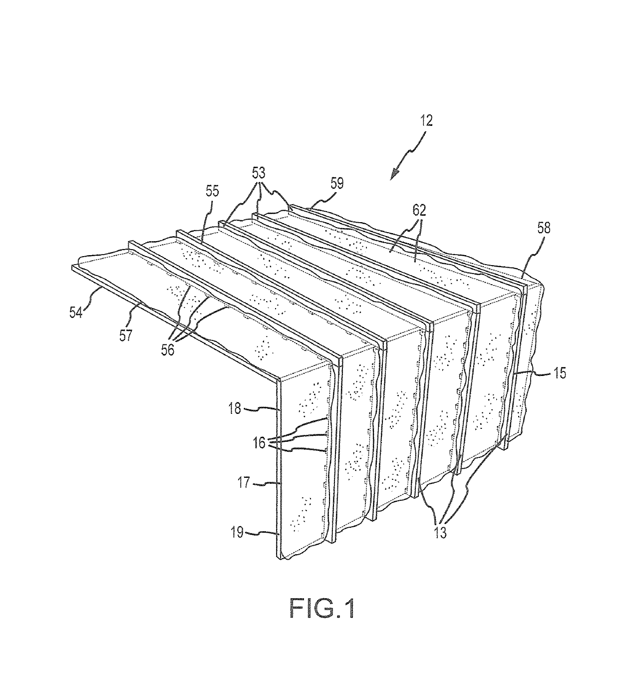
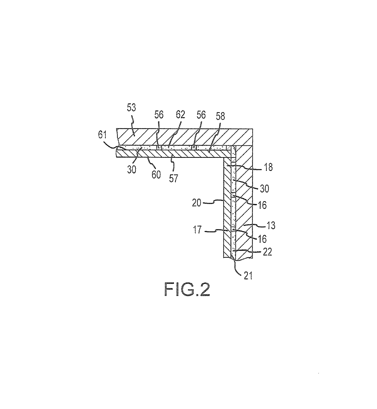
[0017]According to a preferred embodiment, a narrow horizontal top plate is situated along the top ends of the studs. The top plate is “narrow” in the sense that its width (in the dimension of the thickness of the wall) is less than the width of the studs. For example, if the wall studs are 2×6 inches, the top plate is composed of 2×4 inches lumber elements. The roof assemblies are supported upon the top plates; preferably, there is at least one separation saddle element between the bottom surface and of the roof assembly and the top surface of the top plate. The use of narrow top plates along the tops of the walls promotes easy and thorough application of closed-cell spray foam at and over the junctures where adjacent panels come in mutual contact where rood panel assemblies are joined to wall panel assemblies.

Problems solved by technology

This creates gaps or spaces between the studs and the wall panel where the standoffs are not located.
Because this may be unattractive, the user of this method may desire to cover the exterior of the building with some material, but that material would not need to provide any structural support.

Method used


Image

  • Building construction method
  • Building construction method
  • Building construction method

Examples


case 1

tand-offs, 2″ depth of foam

Case 2: No Stand-offs, 2″ depth of foam

case 3

tand-offs, 2.5″ depth of foam

[0086]The truss geometry described above was the same for all three cases. Case 1 and Case 2 can be compared to understand the effect of the stand-offs for the same amount of foaming. (Here, the materials cost of the foam application would be the same.) However, due to the stand-offs, only 1.5-inch depth of foam was adhered to the interior surface of the studs due to the 0.5-inch offset of the stand-offs, while all 2-inch depth of foam in Case 2 was adhered to the interior surface of the studs. Thereafter, Case 3 was also analyzed such that Cases 2 and 3 both had 2-inch foam depth adhered to the interior surfaces of the studs, which required more material cost of foam for Case 3, while leaving the same amount of non-foamed working space for electrical wiring, etc.

[0087]The truss model geometry was substantially as depicted in FIGS. 7 and 8. For Cases 1 and 3, the shear wall truss geometry included stand-offs located with 12-inch spacing on center startin...


PUM


Abstract

A method of constructing a building using wall panel assemblies and roof panel assemblies that are made up of traditional framing materials, such as studs and interior walls, coated with insulating foam, except that the typical exterior sheathing is optional. Because the panel assembly is structurally sound and thermally insulated, the only reason to install an exterior sheath or additional roofing material is for aesthetic or practical purposes. A beneficial mode for readily applying insulating foam to provide for sealably joining roof panel assemblies to wall panel assemblies is disclosed.

Description

CROSS-REFERENCE TO RELATED APPLICATIONS[0001]This application is a continuation-in-part of my co-pending U.S. Utility patent application Ser. No. 15 / 831,234, filed 4 Dec. 2017, which was a continuation-in-part of my U.S. Utility patent application Ser. No. 14 / 822,264, filed 10 Aug. 2015, now U.S. Pat. No. 9,834,923 entitled “Building Construction Method.” Entirety of each of these prior applications is incorporated herein by reference.BACKGROUND OF THE INVENTIONField of the Invention[0002]The present invention relates to building construction methods, particularly to a method and unit that provides energy efficiency and structural soundness in buildings through a foam layer shell application.Background Art[0003]“Light framing” construction is a known construction mode using many small and generally closely spaced members that are assembled by nailing / screwing, and the mode includes balloon, platform and light-steel framing. Light framing building techniques are commonly used, especi...

Claims


Application Information

Patent Timeline
Patent Type & Authority Patents(United States)
IPC IPC(8): E04B1/18E04B2/56E04B1/76E04B1/343
CPCE04B1/18E04B1/7654E04B1/34331E04B2/562E04B1/14E04B1/34321E04B1/34838E04B1/7604E04B1/7675E04B2001/7679Y02B30/90Y02A30/00
Inventor LEPAGE, ROBERT
Owner LEPAGE ROBERT
Why Eureka
Try Eureka