
Apparatus and method using a dual gate TFT structure

a dual-gate tft and apparatus technology, applied in the field of apparatus and methods using a dual-gate tft structure, can solve the problem that the multi-simulation scheme does not provide a signal-to-noise advantage with respect to horizontality

Active Publication Date: 2019-04-23
CARESTREAM HEALTH INC
View PDF9 Cites 1 Cited by
  • Summary
  • Abstract
  • Description
  • Claims
  • Application Information

AI Technical Summary

Benefits of technology

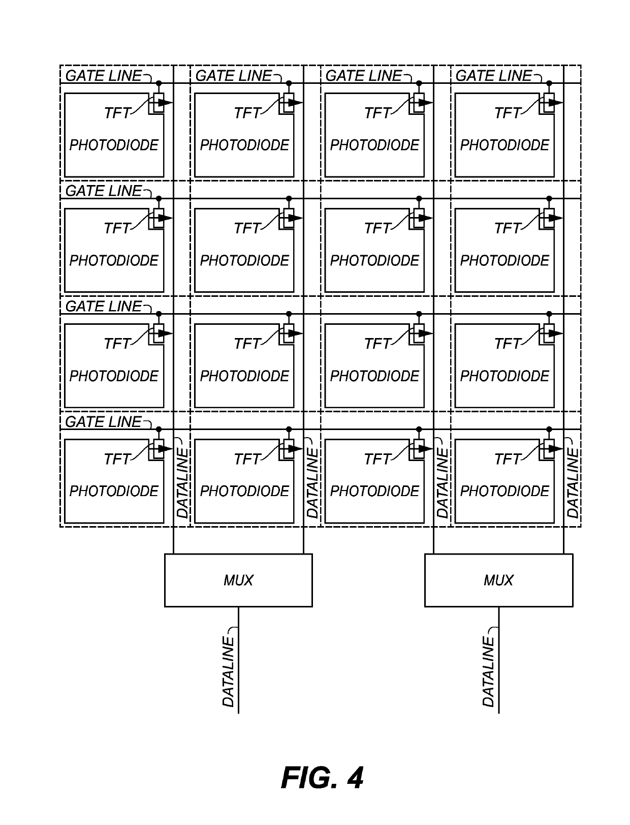
The patent describes a new way of designing a detector with pixels that can reduce the number of data lines and improve the signal-to-noise ratio. This is achieved by connecting the pixels in rows and columns and sharing one common data line. The detector can also have up to twice the number of pixels using a smaller technology. The technical benefits include reducing costs, improved frame-rate, and better sensitivity.

Problems solved by technology

This multiplexing scheme does not provide a signal-to-noise (SNR) advantage with respect to horizontal charge binning due to the fact that charge is shared on two separate data lines (prior to the mux) and data line noise is the dominant noise source in a typical DXD panel.

Method used


Image

  • Apparatus and method using a dual gate TFT structure
  • Apparatus and method using a dual gate TFT structure
  • Apparatus and method using a dual gate TFT structure

Examples


Embodiment Construction

[0038]FIGS. 5A-5B show a comparison of two TFT element structures in cross section and their associated I-V curves (Id drain current vs. gate voltage). The active layer in these devices may comprise IGZO. The bottom portion of FIG. 5A illustrates a common I-V curve depiction for the single (bottom) gate control TFT structure shown in the top portion of FIG. 5A. This bottom gate electrode (BG) is connected to the ROW based readout of a DXD panel. An “OFF” and “ON” voltage for the BG is defined by the detector requirements. In IGZO TFTs, due to the higher mobility compared to a-Si TFTs, the “ON” voltage can also be made much lower than a-Si. The bottom of FIG. 5B illustrates measured I-V characteristics for the dual gate TFT structure shown in the top portion of FIG. 5B. The bottom portion of FIG. 5B illustrates a family of six curves for decreasing top gate voltages in steps of 0, −2, −4, −6, −8, and −10 V, wherein increasingly negative top gate voltage shifts the I-V curve to the ri...


PUM


Abstract

A detector having an array of pixels arranged in columns and rows. Each of the pixels has a photosensor and a switch device. The switch devices in each pair of row-adjacent pixels are connected to a common data line and a common bottom gate line. A pair of top gate lines are each connected to one of the pair of row-adjacent pixels.

Description

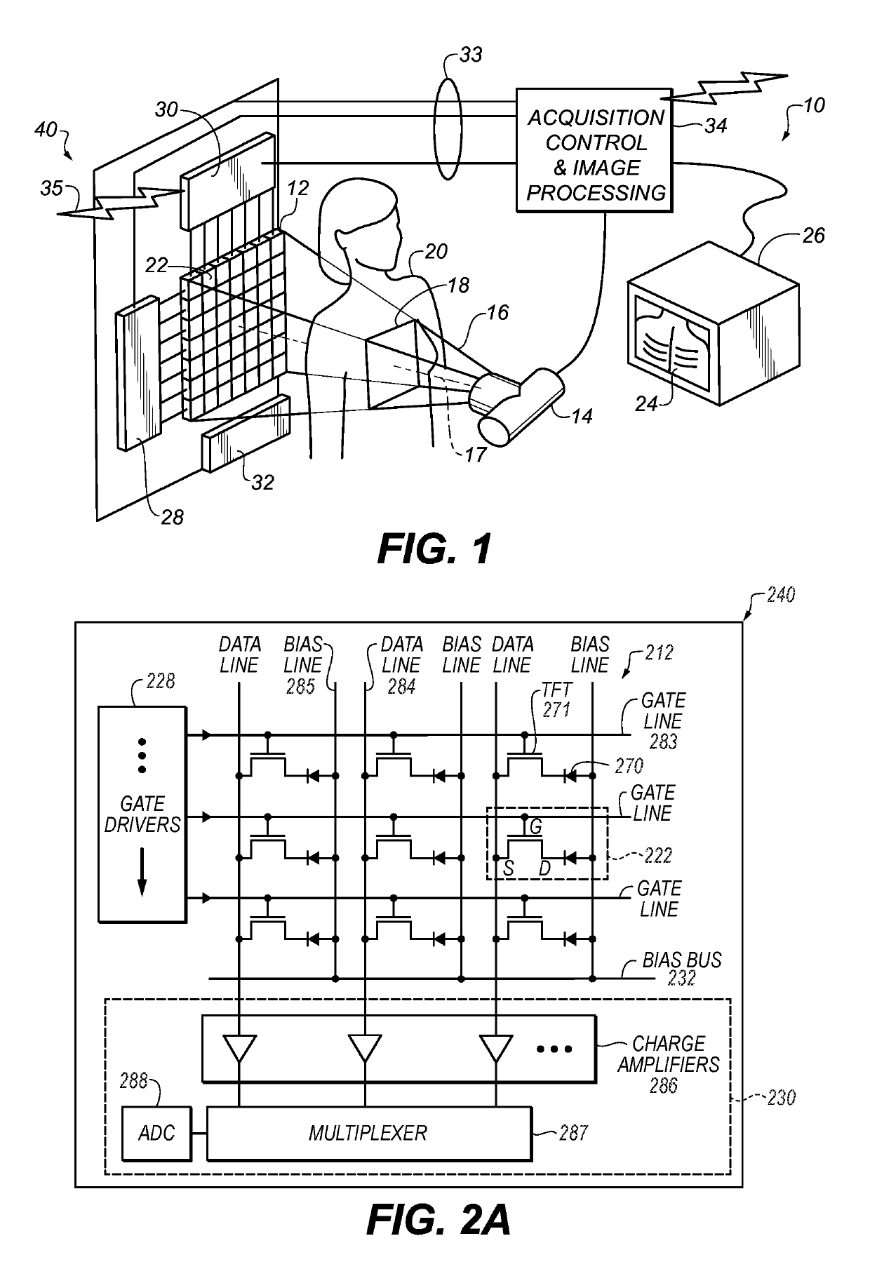
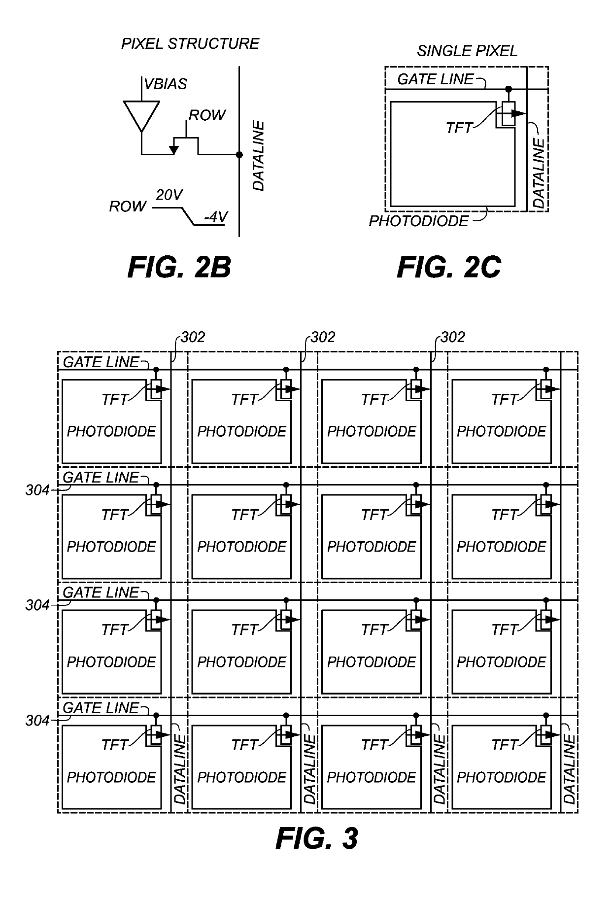
CROSS REFERENCE TO RELATED APPLICATIONS[0001]This application claims priority to U.S. Patent Application Ser. No. 62 / 138,628, filed Mar. 26, 2015, in the name of Mruthyunjaya, and entitled MULTIPLEXING APPARATUS AND METHOD USING A DUAL GATE TFT STRUCTURE.[0002]This application is related in certain respects to U.S. patent application Ser. No. 14 / 972,561, filed Dec. 17, 2015, in the name of Mruthyunjaya, and entitled COMPENSATION CIRCUIT FOR AN X-RAY DETECTOR; and U.S. patent application Ser. No. 14 / 972,628, filed Dec. 17, 2015, in the name of Tredwell, and entitled THRESHOLD VOLTAGE CALIBRATION AND COMPENSATION CIRCUIT FOR A DIGITAL RADIOGRAPHIC DETECTOR, both of which are incorporated herein by reference in their entirety.BACKGROUND OF THE INVENTION[0003]Digital X-ray detectors (DXDs) contain a two-dimensional array of pixel elements. Each pixel element typically contains a diode element and a thin film transistor (TFT) element. The diode element collects light that is converted fr...

Claims


Application Information

Patent Timeline
Patent Type & Authority Patents(United States)
IPC IPC(8): G01T1/24H01L27/146H04N5/32H04N5/374
CPCH01L27/14609G01T1/247H01L27/14614H01L27/14632H01L27/14658H01L27/14687H01L27/14692H04N5/32H04N5/3741H01L27/14641H04N25/766H04N23/30
Inventor MRUTHYUNJAYA, RAVI K.
Owner CARESTREAM HEALTH INC
Learn More