
Box by pin perforating gun system and methods

a perforating gun and pin technology, applied in the direction of drilling pipes, drilling rods, borehole/well accessories, etc., can solve the problems of short communication circuit, difficulty in maintaining close control of gun assembly/loading procedures, and failure of perforating guns or other tools to fire or fail to function appropriately

Active Publication Date: 2019-04-30
HUNTING TITAN
View PDF104 Cites 50 Cited by
  • Summary
  • Abstract
  • Description
  • Claims
  • Application Information

AI Technical Summary

Benefits of technology

This patent aims to solve the issue of wire connections between perforating guns in a well. The invention proposes a solution in the form of a receptacle or resilient connector that makes electrical contact when two guns are joined together. This results in a more efficient and streamlined process of connecting guns in a well.

Problems solved by technology

Because the service company shop often employs a single gun loader, maintaining close control on the gun assembly / loading procedures can become difficult.
When typical a perforating gun is assembled / loaded either at the well site or at a service company shop, there is risk of incorrect assembly or damage to electrical wiring or other components that may cause the perforating gun or other tools to fail to fire or fail to function appropriately.
For example, the threading of a pass-through wire through the gun body or charge holder presents numerous opportunities for the insulation of the wire to be stripped on sharp metal edges resulting in shorts in the communications circuit.
This requires time and manpower at the well site and introduces the possibility of injury or assembly error.

Method used


Image

  • Box by pin perforating gun system and methods
  • Box by pin perforating gun system and methods
  • Box by pin perforating gun system and methods

Examples


Embodiment Construction

[0146]Directional and orientation terms such as upper, lower, top, and bottom are used in this description for convenience and clarity in describing the features of components. However, those terms are not inherently associated with terrestrial concepts of up and down or top and bottom as the described components might be used in a well.

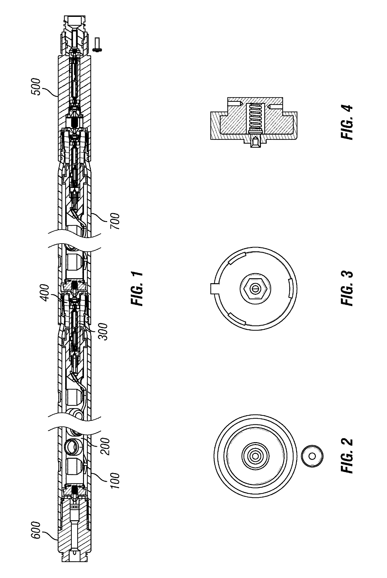
[0147]FIG. 1 illustrates one example embodiment of a perforating gun system. FIG. 1 shows a top gun adapter sub assembly 600, a first perforating gun 100, a second perforating gun 700, and a plug and shoot adapter 500.

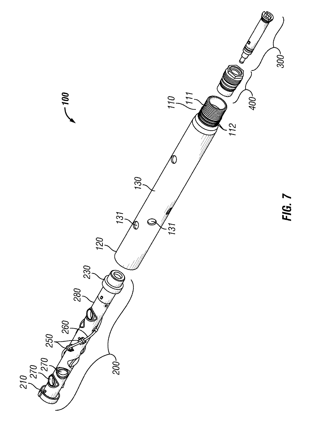
[0148]FIG. 7 shows an exploded view of example perforating gun 100. The perforating gun 100 includes a shaped charge loading tube assembly 200, a cartridge 300, and a baffle 400. Perforating gun 100 includes gun body 130. FIGS. 9, 9A, 9B, and 9C show an example embodiment of gun body 130. Gun body 130 includes a male end 110 and a female end 120. Male end 110 has an external diameter 115, a first internal diameter 113, and a second larg...


PUM


Abstract

A box by pin perforating gun system using swaged down gun bodies, a removable cartridge to hold a detonator and switch, and an insulated charge holder as an electrical feed-through.

Description

BACKGROUND[0001]Generally, when completing a subterranean well for the production of fluids, minerals, or gases from underground reservoirs, several types of tubulars are placed downhole as part of the drilling, exploration, and completions process. These tubulars can include casing, tubing, pipes, liners, and devices conveyed downhole by tubulars of various types. Each well is unique, so combinations of different tubulars may be lowered into a well for a multitude of purposes.[0002]A subsurface or subterranean well transits one or more formations. The formation is a body of rock or strata that contains one or more compositions. The formation is treated as a continuous body. Within the formation hydrocarbon deposits may exist. Typically a wellbore will be drilled from a surface location, placing a hole into a formation of interest. Completion equipment will be put into place, including casing, tubing, and other downhole equipment as needed. Perforating the casing and the formation w...

Claims


Application Information

Patent Timeline
IPC IPC(8): E21B43/1185E21B43/117E21B17/042F42D1/04F42B3/08F42B5/03
CPCE21B43/1185E21B17/042F42D1/043F42B3/08F42B5/035E21B43/117
Inventor BRADLEY, RICHARD WAYNECOLLINS, WILLIAM RICHARDJORDAN, JOHN W.LANE, ANDYLANGFORD, DALELEVINE, CHARLESPUNDOLE, FARAIDOON
Owner HUNTING TITAN
Features
  • Generate Ideas
  • Intellectual Property
  • Life Sciences
  • Materials
  • Tech Scout
  • Unparalleled Data Quality
  • Higher Quality Content
  • 60% Fewer Hallucinations
Learn More